Procedures and Interrupts
Procedures and Interrupts. Chapter 5 Stack Procedure Software Interrupt BIOS-level access DOS-level access Video Display Direct Video access. The Stack. The stack resides in the stack segment (in main memory) who’s segment number is in the SS register

Procedures and Interrupts
E N D
Presentation Transcript
Procedures and Interrupts Chapter 5 Stack Procedure Software Interrupt BIOS-level access DOS-level access Video Display Direct Video access
The Stack • The stack resides in the stack segment (in main memory) who’s segment number is in the SS register • The SP register holds the offset address of the last element added to the stack • If the stack was allocated with the directive .STACK 100h : • Then SP should, initially, contain 100h (pointing to the top of the empty stack)
PUSH (16-bit case) • PUSH source • will decrement SP by 2 • and copy the content of source intoword at SS:SP • little endian: low order byte at lowest offset • Ex: (see figure) • mov ax,06 • push ax • mov ax,0A5h • push ax • This is for a source of type word (reg16 or mem16). • imm16 are allowed only on 286 and later processors)
PUSH (32-bit case) • With a 32-bit operand (.386 directive): • push source • Decrements SP by 4 and copies the content of source into the double word at address SS:SP • Little endian convention. Ex: • mov eax,12345678h • push eax • will decrease SP by 4 and will move: • 78h at SS:SP • 56h at SS:SP+1 • 34h at SS:SP+2 • 12h at SS:SP+4
POP • The POP instruction undoes the action of PUSH • POP destination • For a 16-bit destination operand: • the word at SS:SP is copied into destination • SP is incremented by 2 • For a 32-bit destination operand: • the dword at SS:SP is copied into destination • SP is incremented by 4 • The destination operand cannot be imm
Ex: saving and restoring registers • .data • message db “Hello world $” • .code • push ax ;save AX • push dx ;save DX, SP points to copy of DX • mov ah,9 • mov dx, offset message • int 21h ;prints message • pop dx ;restore DX • pop ax ;restore AX
More Saving and Restoring • PUSHA (.286) pushes AX, CX, DX, BX, SP, BP, SI, DI on stack and POPA pops the same registers in reverse order • PUSHAD (.386) pushes EAX, ECX, EDX, EBX, ESP, EBP, ESI, EDI on stack and POPAD pops the same registers in reverse order • PUSHF and POPF pushes and pops the FLAGS register onto and from the stack • PUSHFD and POPFD (.386) pushes and pops the EFLAGS register onto and from the stack
Procedures • Procedures are defined like this: • name PROC [type] • ... set of instructions... • RET • name ENDP • The “type” is either NEAR or FAR • To transfer control to the procedure “name” we do: • CALL [type PTR] name • RET transfers control to the instr. following CALL • The default for “type” and “type PTR” is: • NEAR: for memory models: tiny, small, compact • FAR: for memory models: medium, large, huge
CALL & RET (NEAR Procedures) • Upon a CALL to a NEAR procedure: • SP is decremented by 2 • The content of IP is copied at SS:SP • this is the offset address of the instruction following CALL (where the procedure must return) • The offset address of the first instruction in the called procedure is copied into IP • this will thus be the next instruction to execute • Upon a RET from a NEAR procedure: • the word at SS:SP is popped into IP (so that SP is automatically incremented by 2) • (the instruction pointed by IP is then executed)
IP IP IP 0006 0080 0009 CALL & RET (NEAR Procedures)
CALL & RET (FAR Procedures) • Upon a CALL to a FAR procedure: • CS and then IP are pushed onto the stack • this is the segment:offset address of the instruction following CALL (where the procedure must return) • The segment:offset address of the first instruction in the called procedure is copied into CS:IP • this will thus be the next instruction to execute • A RET from a FAR procedure effectively does: • POP IP • POP CS • Hence: the instruction at CS:IP is then executed
CS CS CS 2FC0 2FC0 2FC0 IP IP IP 0006 0080 0009 CALL & RET (FAR Procedures)
When does a procedure needs to be FAR? • A NEAR CALL is faster than a FAR CALL • Procedures located in the same segment as the code that CALLs them can be of type NEAR • since the code segment number (in CS) is the same for both the procedure and the caller • Procedures located in a different segment than the code that CALLs them must be of type FAR • since the procedure and the caller have a different code segment number
Using Procedures in irvine.lib • Separately assembled procedures under the .model small will be combined, by the linker, into the same code segment • this is the case for the procedures in irvine.lib • so use a NEAR call to call these procedures • you should also use .model small for your code that call procedures in irvine.lib • other memory models will be used when linking with high level language (HLL) procedures (chap 9 and 13)
Passing Arguments to Procedures • Arguments can be passed to procedures via • the stack: this is the technique used in HLLs. We will use this only later (chap 9) • global variables: the scope of a variable is the .ASM file into which it is defined • must use PUBLIC and EXTRN directive to make them visible to other .ASM files • contrary to modular programming practice • registers: fastest way to pass arguments
Using Procedures • When a procedure returns to the caller it should preserve the content of the registers (except those used to return a value) • should save first the content of the registers that it will modify and restore them just before returning to the caller • Caution on stack usage: • SP points to the return address when entering the procedure. Make sure that this is the case just before executing RET !! • ProcEx.html Break ...
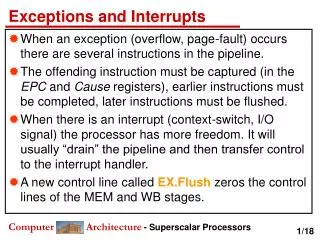
Interrupts • The term interrupt is used in many different ways • A hardware interrupt is a signal generated by any part of the hardware that needs immediate attention of the processor • A software interrupt (sometimes called a Trap) is a call to an Interrupt Service Routine (ISR) of the Operating System (here: either DOS or BIOS) • produced by the instruction INT n in a program • A processor exception is an automatically generated trap in response to an exceptional condition (abnormal program execution). Ex: divide overflow, coprocessor not available...
Hardware Interrupts • When a hardware component (ex: a peripheral device) needs CPU attention, the controller associated with this component sends a Interrupt Request (INTR) signal to the CPU and puts an Interrupt Number (0 to FFh) onto the data bus • The CPU uses this interrupt number to index the interrupt vector table (IVT) located at physical addresses 00000h to 003FFh (pp.33) • Each entry of this table, called an interrupt vector, contains the segment:offset address of the Interrupt Handler (ISR) servicing that interrupt. • To service an interrupt, the CPU transfers control to the corresponding ISR
The Interrupt Vector Table (IVT) • Each entry of the IVT occupies 4 bytes • At entry 0 of the IVT we have the offset address and then the segment address of the ISR handling INT 0 • At entry n of the IVT we have the offset address and then the segment address of the ISR handling INT n
Interrupt Processing • The same mechanisms are used to handle all types of interrupts (hardware, software, exception) • When an interrupt occurs: • The CPU pushes the FLAGS register onto the stack • The CPU pushes onto the stack the far (segment:offset) return address (ie: that of the next instruction) • From the interrupt number N, the CPU fetches the Nth entry of the IVT and transfers control to that ISR • The ISR execute a IRET instruction to return control to the program at the point of interruption (this pops off the stack the far return address and the FLAGS register)
Interrupt Service Routines • A ISR is like a procedure except that: • a transfer to a ISR pushes FLAGS in addition to a far return address • a ISR returns with IRET instead of RET • But since the point of interruption can occur anywhere in a program, it is crucial for a ISR to not modify the content of any register • How to write a ISR and how to initialize the corresponding entry in the IVT? (chap 15) • For now let us examine what are the ISRs that are provided by DOS and BIOS (and how to use them) to perform I/O operations
Common Software Interrupts • Int 10h Video Services • Int 16h Keyboard Services • Int 17h Printer Services • Int 1Ah Time of Day • Int 1Ch User Timer Interrupt • Int 21h DOS Services
MS-DOS Function Calls • A MS-DOS function is called upon the execution of INT 21h • The actual function to be performed depends on the function number stored in AH • about 90 different functions are supported • We have already seen functions 01h, 02h, 09h and 4Ch • We now briefly view some other functions • see more details in section 5.5 of your textbook
Output Functions • 02h: Character Output • 05h: Printer Output • 06h: Direct Output • 09h: String Output
Input Functions • 01h: Filtered Input With Echo • 06h: Direct Input Without Waiting • 07h: Direct Input, No Ctrl-Break • 08h: Direct Input with Ctrl-Break • 0Ah: Buffered Input • 0Bh: Get Input Status • 0Ch: Clear Input Buffer, Invoke Input Function • 3Fh: Read From File or Device
Single Character input (DOS) • For all these functions, the next character in the keyboard buffer is stored in AL • Wait for keystroke: function 6 (with DL=FFh) always returns even when the buffer is empty • Function 1 and 8 will return control to DOS when Ctrl-Break is entered
Ex: AH=06h clear_keyboard Clear_keyboard proc push ax push dx L1: mov ah, 6 mov dl, 0FFh int 21h jnz L1 pop dx pop ax ret clear_keyboard endp
Buffered Input (DOS) • Function 0Ah reads (from stdin) a string of up to 255 characters and stores it in a buffer • User input is terminated with 0Dh (CR) • Non ASCII keys (ex: PgUp, arrows, Fn...) are filtered out and Ctrl-Break is active • DX contains the offset of the Buffer • 1st char = max number of char allowed (including 0Dh) • 2nd char = number of chars actually entered (excluding 0Dh)
Ex: Using buffered input function 0Ah • .data • keyboardArea label byte • maxkeys db 32 ;max # chars allowed • charsInput db ? ;# of chars actually entered • buffer db 32 dup('0') ;holds input string • .code • mov ah,0Ah • mov dx,offset keyboardArea • int 21h • the CR (0Dh) is the last char entered in the buffer
Date/Time Functions cx: year dh: month dl: day • 2Ah: Get Date • 2Bh: Set Date • 2Ch: Get Time • 2Dh: Set Time ch: hour cl: minute dh: second Break ...
Keyboard Keys • ASCII keys: • those that have an ASCII code: letters, digits, punctuation’s, arithmitic’s, Esc, CR, Bksp, Tab • Shift Keys: • normally used in combination with another key: left and right shifts, Caps Lock, Ctrl, Alt, Num Lock, Scroll Lock • Function Keys: • used in programs to perform special functions: F1-F12, arrows, Home, PgUp, PgDn, End, Ins, Del
Scan Codes • Only ASCII keys have an ASCII code but all keys have a SCAN CODE (1byte). See scancodes.html • When we strike a key: • The keyboard interrupts (INT 9h) the CPU and sends the Scan Code to I/O port 60h • The BIOS INT 9h reads this I/O port and uses the scan code to index a table to get the ASCII code. Both codes are sent to the keyboard buffer only if it is not a shift key (used alone) • For each word in the keyboard buffer: • low byte = ASCII code of the key, or 0 if it is not an ASCII key • high byte = Scan Code of key
BIOS input function INT 16h • When AH=10h, INT 16h will load AX with the next word in the keyboard buffer: • mov ah,10h • int 16h ;AH = Scan Code, AL = ASCII code • The input character will not be echoed on screen • Useful for reading (and identify) the function key pressed by the user • they can be identified only with their scan code • Keyboard input cannot be redirected on the DOS command line (unlike INT 21h)
Video Adapters • Screen display is controlled by a video adapter which consists of: • A memory (video buffer) which contains all the information displayed on screen • A video controller that displays on screen the content of the video buffer • Typical resolutions (in pixels X pixels): • 640 X 480 (standard VGA) • 800 X 600 (super VGA) • 1024 X 768 (extended VGA) • ....(higher resolutions)....
Video Modes • We have two classes of video modes • graphic modes: used to display arbitrary graphics, including text (not discussed here) • text modes: only characters (from the IBM extended ASCII character set) can be displayed. (the subject till the end of chapter) • From the many available text modes (mode 0, 1, 2, 3, 7) we discuss only mode 3 (most important one) • displays text on 80 columns and 25 rows • first row = row 0 = top of the screen • first column = column 0 = left of screen • 16 colors are available
Video Pages • Each character displayed is represented by 1 word • low order byte = ASCII code (IBM extended) • high order byte = Attribute Byte (specify how the character will be displayed) • Each of these words is stored in the video buffer starting at physical address B80000h • One screen of text (80 X 25 X 2 = 4000 bytes) requires 1 video page of 4KB • VGA (and better) adapters can hold 8 video pages: page 0 to 7
Video Pages (cont.) • only the active page is displayed: • the first word of the page displays the character at the upper left corner: (row,column) = (0,0) • the second word displays the character at (row, column) = (1,0) • the 3rd word displays the char at (2,0)... • ...the last word displays the char at (24,79) • (other pages can be modified while the active page is being displayed)
The Attribute Byte • The foreground bits determine the color of the character • The background bits determine the color of the background • The msb of foreground is an intensity bit • The blinking bit applies only to foreground
Foreground Colors • Background colors are the same as foreground colors with msb = 0
Ways to write on the screen • We can write directly to the video buffer to display text. See Direct2Videomem.html • this is the fastest method but also the most complex. Cannot redirect the output with DOS. • We can use DOS INT 21h functions • very slow to go through DOS • Output can be redirected (DOS command line) • We can use BIOS-LEVEL INT 10h functions • faster than DOS but slower than direct access • Cannot redirect the output
Some BIOS INT 10h functions • Function 00h: set video mode. AL contains the desired text mode. Ex: • mov ah,0 ;set video mode • mov al,3 ;choose text mode 3 • int 10h ;mode is set • Function 05h: set active display page. AL contains the desired page number. Ex: • mov ah,5 ;set display page • mov al,1 ;page # to display • int 10h ;display chosen page • Page 0 is the usual page displayed by DOS • Each page has its own cursor.
Some BIOS INT 10h functions (cont.) • Function 02h: Set cursor position. • Input: BH = chosen page number • DH = chosen row, DL = chosen column • mov ah,2 ;set cursor position • mov dh,10 ;row 10 • mov dl,18 ;column 18 • int 10h ;cursor is set • Function 03h: Get cursor position. • Input: BH = chosen page number • Output: DH = row, DL = column • mov ah,3 ;get cursor position • int 10h ;DH=row, DL=column
Other BIOS INT 10h functions • See chap 5 of textbook for details • 08h: Read Character and Attribute at cursor position • 09h: Set Character and Attribute at cursor position • 06h: Scroll window up (by n rows) • 07h: Scroll window down (by n rows) • ...and many more!!
main proc 0000 mov ax, 8 0003 push ax 0004 call Factorial 0007 mov ax, 4C00h 000A int 21h main endp Factorial proc 000C push bp 000D mov bp, sp 000F mov ax, [bp+4] 0012 cmp ax, 1 0015 ja L1 0017 mov ax, 1 001A jmp L2 001D L1: dec ax 001E push ax 001F call Factorial 0022 mov bx, [bp+4] 0025 mul bx 0027 L2: pop bp 0028 ret 2 Factorial endp Trace Program Recursion