Download
1 / 19
750 likes | 1.74k Vues
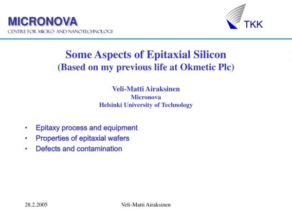
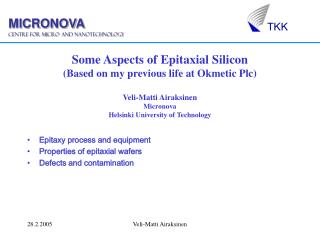
Some Aspects of Epitaxial Silicon (Based on my previous life at Okmetic Plc) Veli-Matti Airaksinen Micronova Helsinki University of Technology. Epitaxy process and equipment Properties of epitaxial wafers Defects and contamination. P-type epi. P + substrate. Epitaxy.

E N D
Some Aspects of Epitaxial Silicon(Based on my previous life at Okmetic Plc)Veli-Matti AiraksinenMicronovaHelsinki University of Technology • Epitaxy process and equipment • Properties of epitaxial wafers • Defects and contamination Veli-Matti Airaksinen
P-type epi P+ substrate Epitaxy • Epitaxy = Deposition of single crystalline layer of semiconductor. • Deposition is done on a single crystal substrate (silicon wafer). • High temperature process 700- 1200oC. • Deposition from vapour phase with CVD. • Precursors SiCl4, SiHCl3, SiH2Cl2 or SiH4. • More than 70% of all silicon wafers get epi on them. • Two types of epi: blanket or in-line. • Atmospheric process for blanket epi. Reduced pressure often used for in-line epi. Veli-Matti Airaksinen
The epitaxial layer lacks some of the impurities (C, O) and defects (COPs) of the substrate wafer. The resistivity of the epi layer can differ from the substrate by a factor of 10000. The electrical interface between substrate and epilayer is abrupt and sharp. The resistivity of the epi layer is reproducible and uniform. The thickness of the epi layer is very reproducible and uniform. Complicated multilayer structures are possible. And it’s relatively expensive. Features of epitaxial wafers Veli-Matti Airaksinen
Two types of reactors: single wafer and batch. Process chamber made out of fused silica. During processing wafer rests on a SiC coated graphite susceptor. Heating inductively or with lamps. Reactors Veli-Matti Airaksinen
Advantages of the single wafer reactor • Heating by IR lamps: fast • Horizontal laminar gas flow: less autodoping • Very low particle levels • Excellent thermal profile: less slip • Excellent stability and uniformity • Lower cost for large wafers and thin epi Veli-Matti Airaksinen
Reactor etched clean with HCl prior to deposition. Wafer(s) loaded in by wafer handler (or manually in batch process). Native oxide removal at 1120-1200 oC. (Other techniques used for low temperature epi processing.) Typical epi deposit temperature 1080- 1190 oC with trichlorosilane (TCS) and 950- 1080 oC with dichlorosilane (DCS). H2 used as carrier gas. Dopants: PH3, AsH3 (n-type) or B2H6 (p-type). Deposition rate:4 - 4.5 µm/min (TCS) and 1 - 1.5 µm/min (DCS) Total process time: 8 minutes for 10 µm epi (TCS process). Process Veli-Matti Airaksinen
Deposit rate and temperature • Epi growth rate depends on temperature. • High growth temperature is also advantageous due to reduced stacking faults. Veli-Matti Airaksinen
Technology Use Epi structure Typical thickness (µm) Typical resistivity (ohm-cm) Advantages Comments CMOS Digital Ics p/P+ 5-20 5-10 Minimize latch-up Backsealing! MOS Power devices n/N+ 10-20 5-10 Thick doped layer MOS CCD n/N- 20-30 25-35 Uniformity, low leakage Analog bipolar Amplifiers, Power devices p/P+ 10-100 1-40 Thick doped layer Analog bipolar Optical, X-ray detectors n/N+ 30-40 300-2000 High resistivity, low leakage Backsealing! MEMS Etch stop, active layer of device n/P p/P++/N- 7-15 1-10 Uniform layer, abrupt interface Usually DSP-wafer Who uses epi? Veli-Matti Airaksinen
Important specifications for epi wafers • Epi thickness. • Thickness variation (within wafer and wafer-to-wafer). • Dopant. • Epi resistivity. • Resistivity variation (within wafer and wafer-to-wafer). • Defect levels: particles and stacking faults. • Allowed metallic contamination level. Veli-Matti Airaksinen
Single Wafer Process Performance • Typical • Thickness uniformity (wafer-to-wafer) 1.0% • Resistivity uniformity (wafer-to-wafer) 4.0% • Best • Thickness uniformity (wafer-to-wafer) 0.60% • Thickness uniformity (within wafer) 0.85% • Resistivity uniformity (wafer-to-wafer): <10 Ohm-cm 2.0% 10-50 Ohm-cm 4.5% • Resistivity uniformity (within wafer): <10 Ohm-cm 1.5% 10-50 Ohm-cm 3.0% Veli-Matti Airaksinen
Resistivity range (in production) Veli-Matti Airaksinen
Problems with Epitaxial Wafers • Autodoping. • Surface defects (stacking faults). • Metallic contamination Veli-Matti Airaksinen
Autodoping • Autodoping: unintentional doping due to background impurities (from substrate, reactor, gases…) • Autodoping is reduced primarily by raising hydrogen flow which increases the potential for slip and resistivity uniformity problems. • For lowest background doping (high resistivity), a high growth rate is essential. • Resistivities of 1000-2000 ohm-cm are routinely produced on Sb-doped substrates. • Resistivities of up to 10000 ohm-cm are technically possible. Veli-Matti Airaksinen
Mound Stacking fault Pyramid Spike • Stacking faults • Also called pyramids, hillocks or mounds. • Defects originating from the epi-substrate interface. • Typically 0 - 2 SFs on a wafer. • Affect subsequent processing, especially lithography and wafer bonding. • Cause high leakage currents if within the active area of device. Veli-Matti Airaksinen
Stacking fault is caused by a defect on the starting wafer surface (particle, damage, oxide island...). • Quality of starting surface is crucial for the prevention of SFs. • SF grows on the (111) plane. • Size is proportional to epi thickness. Veli-Matti Airaksinen
Metallic Contamination • Leakage currents can be significantly increased by metals. • In most applications most contamination occurs during device processing. Metal levels are controlled by gettering. • For some applications (i.e. detectors) low metal levels have been found to be important. • Due to measurement problems knowledge about contaminants and contamination sources is patchy. Veli-Matti Airaksinen
Metallic Contamination • Important contaminants: Fe, possibly Mo and Ti, occasionally Cu and Ni. • Cu and Ni are very fast diffusers; Fe moderately fast; Mo and Ti slow. • Behaviour of Fe is known best due to easy, quantitative measurement in p-type material using recombination lifetime. • Recently quantitatitive techniques for Cu have been developed. Veli-Matti Airaksinen
Metallic Contamination: Fe, Mo, Ti • Epi process is inherently clean due to high concentration of Cl and H2 in the ambient. • Normally epi contains a slow diffusing contaminant (either Mo or Ti) in significant concentrations. The source of this contaminant is not known and it cannot be controlled. • Fe contamination occurs due to contamination from equipment: Leaks in gas system (Cl containing gas), pinholes in SiC coating of susceptor, or faulty pre-epi cleaning. Veli-Matti Airaksinen
Metallic Contamination: Cu and Ni • Fast diffusers (Cu and Ni) tend to segregate to wafer surface during cooldown. • Cu, however, can also precipitate in n-type silicon. (Formation of Cu precipitates is controlled by the Fermi-level.) • Source of Cu is polishing slurry. P-type substrates may contain relatively high levels of Cu! Veli-Matti Airaksinen