Polarized Positron Source using Backward Compton Scattering
Polarized Positron Source using Backward Compton Scattering. Tohru Takahashi Hiroshima University 高橋 徹 広島大学. 2007/11/5. Why polarized positrons. electrons are polarized,,,,,, choose helicity of its counter part. if unpolarized e+. a half of the beam is thrown away.

Polarized Positron Source using Backward Compton Scattering
E N D
Presentation Transcript
Polarized Positron Source using Backward Compton Scattering Tohru Takahashi Hiroshima University 高橋 徹 広島大学 2007/11/5 T.Takahashi Hiroshima
Why polarized positrons electrons are polarized,,,,,, choose helicity of its counter part if unpolarized e+ a half of the beam is thrown away T.Takahashi Hiroshima
electon beam is polarized but,,,, In principle, we can suppress this by polarized electrons if we want but T.Takahashi Hiroshima
Positron polarization Positron polarization helps much to : increase luminosity effectively suppress background physics is sensitive to the polarization polarization (either e- or e+) has to be well controlled
J.Hewett LCWS07 SUSY, New Phys. summary ILC: e+ Polarization from Beginning? To use the e+ polarization for physics we strongly ask to provide a machine with flexible helicity reversal also for the positron beam No or veryrare reversal of e+ helicity could be worse than no e+ polarization • Reminder: Positron Pol is important for numerous physics channels • Gain in production rate • Reduction of Bckgrnd • Access to new channels Positron Pol WG
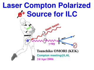
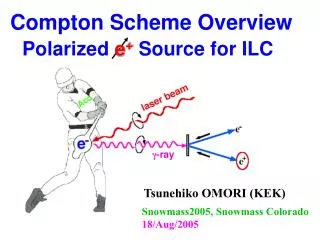
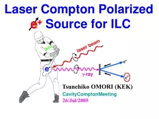
How to get them Compton Helical Undulator L>150m Ee~150GeV Laser Ee~GeV
pros and cons Compton based positron polarization • independent of main linac • good capability of controlling polarization • R& D issues • how to get enough intensity T.Takahashi Hiroshima
Proof of Principle at KEK - ATF T.Takahashi Hiroshima
To meet ILC requirements • Requirements for ILC • 2x10¹⁰/bunch • ~3000 bunches/train • 5Hz • ideas to meet requirement • Single pass • Linac based • Recycling e- and Lasers • e- Storage ring + optical cavity • Energy Recovery Linac(ERL) + optical cavity T.Takahashi Hiroshima
Linac Scheme • Co2 laser 1J • Single pass 5x10¹¹g 2x10¹⁰ e+ 4GeV, 1A 15MeV e+ V.Yakimenko ~2m directly creates enough e+ high current e- source, regenerative laser cavity ? T.Takahashi Hiroshima
Compton Ring Scheme • electron bunches stored in the ring • laser pluses are stacked in the optical cavities -> 600mJ • stacking 100 bunches on a same bucket in the DR -> 2.4x10¹⁰ e/bunch target 2.4x10⁸ e+ 1.7x10¹⁰ g capture system 6.15ns Optical Cavities damping ring 1.3 GeV e- source Electron Storage Ring high repetion e- source optical cavity, pulse staking, e- quality in ring main linac ? T.Takahashi Hiroshima
ERL Scheme • get fresh e bunches by ERL • laser pluses are stacked in the optical cavities -> 600mJ • continues stacking ~1000 bunches on a same bucket in the DR -> 2x10¹⁰ e/bunch target 2x10⁷ e+ 6.4x10⁹ g capture system Optical Cavities 6.15ns damping ring Energy Recovery Linac main linac e- gun dump high repetition e-, fresh e- each turn, higher pol. optical cavity, ERL, bunch stacking ? T.Takahashi Hiroshima
R&D times omori CR/ERL simulations studies (Kharkov, LAL, JAEA, KEK) design studies beam dynamics studies Optical Cavity (LAL,IHEP, Hiroshima, KEK) experimental R/D e+ capture (LAL, ANL) We will start collaboration with KEKB upgrade study e+ stacking in DR (CERN) Basic beam dynamics studies Laser Fiber laser / Mode-lock laser (cooperation with companies) CO2 laser (BNL)
Laser pulse stacking cavity 325 MHz 325 MHz Omori Laser-electron small crossing angle Laser bunches Lcav = n Lcav = m Llaser Cavity Enhancement Factor = 1000 - 105
Prototypes 2-mirror cavity (Hiroshima/KEK) 4-mirror cavity (LAL) high enhancement very small spot size complicated control moderate enhancement small spot size simple control accumulate experiences w/ beam at ATF to ATF later
Experimental R/D at ATF • 2 mirror FP • Lcav = 420 mm • for 2.8ns bunch • spacing ATF at KEK
installed into the ATF DR last September
Pulse Stacking Cavity for gg colliders • 100 m long pulse stacking cavity surrounding the detector opticalcavity for gg collisers = (pluse + small spot size + high power) + (larger scale) ~ polarized positron + gravitational wave K. Moeing T.Takahashi Hiroshima
Summary • Polartized Positron is useful and preferable to be implemented at the early stage of the ILC • Laser-Compton scheme looks attractive • Many common efforts can be shared in various applications. • State-of-the-art technologies • Laser, Optical cavities,ERL Stay tuned and Join us
4 mirror cavity at LAL beam Interaction point e- beam e- beam tube laser injection intend to be installed into ATF POSIPOL 2007
Proof of Princple at KEK - ATF T.Takahashi Hiroshima
Pros and Cons • Linac Scheme • High g gen by one pass; no stacking in DR • 10nc 5ps e- source • high power Co2 laser: regenerative cavity • Ring Compton • moderate laser power w/ optical cavity • 100 stacking • optical cavity R&D • beam life, stability on the Compton Ring • Crab crossing? • ERL • moderate laser power w/ optical cavity • high g yield /w stacking • higher polarization • 200 ~ 1000 staking • optical cavity R&D • Energy recovery after compton Optical cavity bunch stacking seems T.Takahashi Hiroshima
CO2 oscillator 200ps 150ns Ge 1mJ 5ps 10mJ 5ps from YAG laser PC PC TFP 10mJ 5ps 300mJ 5 ps 2x30mJ 1J IP#1 IP#5 e- CO2 Laser system for ILC Kerr generator intra-cavity pulse circulation : • pulse length 5 ps • energy per pulse 1 J • period inside pulse train 12 ns • total train duration 1.2 s • pulses/train 100 • train repetition rate 150 Hz • Cumulative rep. rate 15 kHz • Cumulative average power 15 kW
Positron Sources electron positron Polarized Electron source Positron Source T.Takahashi Hiroshima
Pros and Cons Compton Indepedence need 150GeV e- from main linace independent of main linac Helical Undulator Tunability need deceleration for low energy operation no problem Pol. flip not foreseen yet no problem e+ intensity OK? intense g bunch stacking T.Takahashi Hiroshima
Principle of Pol. e+ generationby Compton Scattering laser Omori T.Takahashi Hiroshima