HDL-Based Design Using Verilog: Combinational Logic Circuit Implementation
This tutorial guides you in using Verilog and Modelsim to create a simple combinational logic circuit. Learn implementation methods, including automatic module generation and user free input design. Follow step-by-step instructions for project setup, source creation, test bench configuration, and waveform initialization. Verify the logic function and simulate the behavioral model. Enhance your Verilog skills with practical examples and hands-on exercises.


HDL-Based Design Using Verilog: Combinational Logic Circuit Implementation
E N D
Presentation Transcript
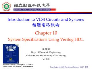
Chapter 05Tutorial Using HDL Based Design Verilog Language
Objective • This tutorial will give you exposure to using HDL based design • Using Verilog and Modelsim for simulating the functional design • This tutorial shows you how to create, using Verilog, a simple combinational logic circuit design
Logic Function F=(x&~y)|(y|z)
Implementation Methods • Method 1: Using the automatic module generator • Method 2: Using the user free input
Method 1 • Using the automatic module generator
Method 2 • Using the user free input
File Name: “complogic1.v” • Module nameand File name must the same. 10