Download
1 / 18
190 likes | 301 Vues
This study explores reverse annealing in high-resistivity ACIS CCDs, focusing on the effects of irradiation and temperature variations on charge transfer inefficiency (CTI). Ground experiments conducted in 2002 and 2005 aimed to model the CTI increases observed during flight and laboratory conditions. The results showed significant discrepancies, highlighting the role of carbon impurities and their behavior during annealing cycles. The findings also indicate the influence of proton energies on CCD performance, leading to future plans for continued research and experimental validation.

E N D
Physics of reverse annealing in high-resistivity ACIS Chandra CCDs Catherine E. Grant (MIT) Bev LaMarr, Gregory Prigozhin, Steve Kissel, Stephen Brown, Mark Bautz
(Brief) Description of ACIS CCDs Flight experience with irradiation/annealing First ground experiment in 2002 Experimental setup in 2005 Data analysis results Sources of systematic errors Summary & future plans Talk Outline
ACIS CCDs • Framestore-transfer • High-resistivity float-zone silicon • Depletion depth: 50-75 mm • 24 mm pixels • 40 msec/pix image-to-framestore transfer rate • Four output nodes 105 pix/s • 3.2 sec nominal frame time
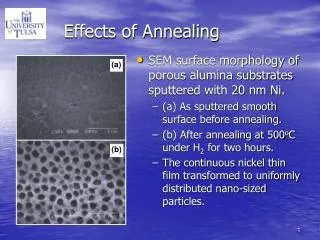
Displacement damage in imaging array Charge transfer inefficiency (CTI) ~ 1-2 x 10⁻⁴ at 6 keV No damage in framestore and serial-transfer arrays No damage to back-illuminated CCDs Believed to be due to soft protons (~200 keV) scattered by mirror during radiation belt passages After focal plane was warmed from –100°C to +30°C for 8 hours, CTI increased by 34% 1999 flight experience with irradiation and annealing
Designed to duplicate flight experience Low-temperature irradiation CCD at –100°C; 120 keV protons 8-hour +30°C annealing cycle CTI increased by 150% Much larger than flight increase (34%) Possible causes: variations between CCDs, different irradiating particle spectrum, ? See Bautz, et al. 2005, IEEE Trans. Nucl. Sci, 52(2), 519 Laboratory experiment 2002
Proposed “Model” for CTI Increase from Annealing • One possible model • Reverse annealing of carbon impurities causes CTI increase during bakeout. • Expect chip-to-chip variations in carbon concentration to cause variations in CTI increase. • Measurements of carbon concentration show much smaller variation than required by differences between 2002 laboratory & flight results. • Schematic of silicon lattice changes during irradiation & bake • Si-Si-C-Si-Si • | | | | | • Si-Si-Si-P-Si • | | | | | • Si-Si-Si-Si-Si • -Si-Si-Si-Si • | C | | | • Si-Si-Si-P-Si • | | | | | • Si-Si-Si-Si-Si • -Si-Si-Si-Si • | | | | | • Si-Si-Si-CP-Si • | | | | | • Si-Si-Si-Si-Si • Pre-irradiation: • P impurites intentionally implanted • C impurities benign • CTI perfect • Post-irradiation, pre-bake: • Si displaced (some CTI increase) • C impurites displaced to benign locations; don’t affect CTI • C can’t migrate at low temp. • CTI somewhat greater • Post-irradiation, post-bake: • C migrates during bake & bonds to P (or C) causing additional traps • CTI increases due to bake ACIS Page 6
Designed to better explore parameter space and understand why flight and ground experience differed Six front-illuminated CCDs 5 from ACIS backup focal plane 1 from 2002 experiment (only 2 quadrants were used) Four proton energies Three types of annealing cycle 8-hour +30C (like flight and 2002) Long duration +30C anneal (over 100 hrs) Multi-T isochronal (1-hr at 0°C, +10°C, +20°C, +30°C) Laboratory experiment 2005
2 MeV van de Graaff accelerator at GSFC radiation lab Proton energies of 100, 120, 180 and 400 keV Dosimetry via surface barrier detector between accelerator and CCDs Dose chosen to cause (pre-anneal) CTI ~ 10-4 CCDs irradiated cold (–100°C) and powered off Experiment Details: Irradiation
Experimental Details: Camera • Camera holds two CCDs side by side • Framestore shielded • Slit-shaped baffle confined beam (3.5mm x 12 mm)
Experimental Details: Beamline Dosimeter 55Fe source Accelerator CCD chamber Flexible bellows Gate valve
Irradiation Pattern • Pivoting CCD chamber • Beam confined by slit • Beam fits within one readout quadrant • CCD aligned by directly imaging low-flux proton beam
Cool CCD to –100°C; measure CTI Irradiate CCD quadrant (x 4) Select energy; align proton beam with low-flux CCD images Irradiate quadrant (CCD power off) periodically monitoring flux w/ beam monitor Measure CTI Perform annealing cycle (one of three types) Cool CCD to –100°C; measure CTI Experimental Procedure
Fractional CTI increase due to annealing: R = DCTIannealing/DCTIirradiation Two (known) sources of systematic error: Temperature variations Post-irradiation CTI relaxation Correct where possible; increase error budget to compensate CTI Measurements
Anomalous Annealing Results • Averaged over all CCD quadrants • Weak dependence on proton energy • Result similar to flight, 2002 experiment is highly discrepant
Long Duration Annealing • Anneal at +30°C for increasingly longer intervals • Maximum CTI increase after 8 hours
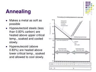
Multi-T Isochronal Annealing • Test sensitivity of annealing CTI increase to temperature • 1-hour each at 0°C, +10°C, +20°C, +30°C • CTI only increases after Tanneal reaches +30°C • A puzzle! - CTI initially decreases
Cannot be due to: Proton energies (dependence is too weak) CCD variations one CCD was irradiated/annealed in both ground experiments - no significant difference from other five CCDs in 2005 Temperature differences? Possibly Camera setups, temperature sensor position different CTI measurements indicate CCD was ~5°C warmer in 2002 than 2005 If CTI temperature dependence is different pre- and post-annealing, R is also dependent on temperature Why was 2002 different from 2005?
Six CCDs irradiated cold by soft protons Room temperature annealing increases CTI Fractional increase due to annealing ~ 0.2 Time constant for annealing CTI increase less than 8 hours CTI increase requires Tanneal ≥ +30°C Plan to study charge in trailing pixels May help explain isochronal annealing CTI decrease May better validate physical model Summary & Future Plans