Analysis of Tilting Pad Thrust Bearing Dynamics and Viscosity Measurement Techniques
This document details the analysis of a tilting pad thrust bearing, including measurements of critical dimensions such as h1, h2, L, and B. It explores the pressure differential on the x-axis, calculating maximum separation height and corresponding load using dynamic viscosity and velocity approximations. Additionally, it covers the principles of heat generation in bearings, flow dynamics of lubricants, and viscosity determination using the capillary tube method. Theoretical equations and references provide a comprehensive understanding of bearing mechanics and fluid dynamics.

Analysis of Tilting Pad Thrust Bearing Dynamics and Viscosity Measurement Techniques
E N D
Presentation Transcript
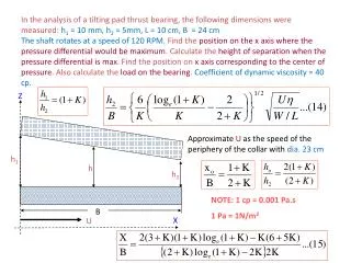
In the analysis of a tilting pad thrust bearing, the following dimensions were measured: h1 = 10 mm, h2= 5mm, L = 10 cm, B = 24 cmThe shaft rotates at a speed of 120 RPM. Find the position on the x axis where the pressure differential would be maximum. Calculate the height of separation when the pressure differential is max. Find the position on x axis corresponding to the center of pressure. Also calculate the load on the bearing. Coefficient of dynamic viscosity = 40 cp. Z Approximate U as the speed of the periphery of the collar with dia. 23 cm h1 h h2 NOTE: 1 cp = 0.001 Pa.s 1 Pa = 1N/m2 B X U
1+k = h1/h2 = 10/5 = 2, k = 1 Xo/B= (1+k)/(2+k) = 2/3, xo = 24x2/3 = 16 cm ho=h2[2(1+k)/2+k] = 5(2)(2)/3 = 20/3 = 6.66 mm = 13.71 cm We need to find load W from the equation
Substituting the values we get Therefore W = (0.42 x 0.076/0.021)2 ~2.3 N
Temperature rise in tilting pad bearing • The rate of work done on the lubricant is the frictional force F multiplied by the velocity U • It can be approximated (especially at high speeds) that all the heat is removed by the oil and no heat is removed by the pad or runner • Hence if the temperature rise is Dt, the density of oil rand its specific heat capacity is c, the energy balance, with J as the mechanical equivalent of heat, we get
Now where ho is the distance of separation when the pressure is maximum And Therefore Friction is given by
Tilting pad bearing- Temperature rise In non-dimensional form, the friction would be From the load equation, Where W* is the non-dimensional load Substituting these values into the energy balance equation we get temperature rise
Ball thrust bearings Housing collar (attaches to housing and is stationary) Shaft collar (attaches to shaft and rotates) Radial load Axial load Inner race Outer race Radial ball/roller bearing- takes on radial loads Shaft is attached to inner race while outer race is attached to machinery housing Inner race rotates with shaft while outer race remains stationary Thrust ball bearing - takes on axial loads
Tapered roller bearings(takes on radial as well as thrust/axial loads) Radial load Outer race Axial load Inner race Ref: http://www.jtekt.co.jp/e/company/news/images/20060404_3e.jpg
Viscosity determination- capillary tube method • Consider steady laminar flow of an incompressible fluid of density r through a long vertical tube of radius R • The flow may be assumed to be similar to sliding of numerous cylindrical shells Force of flow Flow takes place due to pressure drop Viscous drag
Force balance on a fluid shell element Momentum in by flow Pressure p1 • Flow takes place from a region of higher pressure to a region of lower pressure • The forces acting on the shell element are: • Pressure force • Gravitational force • Shear stress r R Tube wall l Momentum out by flow Pressure p2
Forces on a cylindrical fluid element Momentum in by flow Pressure p1 Shear force at surface at radius r = 2prltr Shear force at outer surface of element = -2p(r + Dr)ltr+Dr Pressure force at top (z = 0) = p12prDr Pressure force at bottom (z = l) = -p22prDr Gravity force on shell element = 2prDrlrg Wheretr and tr+ Dr are the shear stresses at r and r + Dr respectively Upward forces have been indicated with a negative sign r R l r+Dr Pressure p2 Momentum out by flow
Equilibrium of the forces From the equilibrium of dynamic forces we have: Which reduces to: or p1 – (p2 – rgl) is the pressure difference Dp causing flow Hence,
Shear stress on element at radius r From previous slide Integrating we get where A is a constant of integration From theory on shear flow in laminar region, the shear stress is maximum at the center line (where r = 0). Therefore When r = 0,dtr/dr = 0, which gives A = 0. Therefore
Velocity in terms of radius From Newton’s law of viscosity The negative sign is incorporated because the velocity decreases with increase in radius. Velocity is zero at surface of tube and maximum at center Hence On integrating we get: At r = R, u = 0. Therefore
Max. velocity and avg. velocity Hence we get the expression for velocity in terms of radius as From the above expression it is clear that the velocity profile is parabolic and is maximum at r = 0. The average velocity is half the maximum velocity. Therefore
Expression for viscosity The volume rate of flow Q = Average velocity x Area This is known as Hagen-Poiseuille law and can be used to determine the viscosity. Therefore Where V is the volume of flow in time t