Design and Implementation of a Scalable LED Matrix Controller
This project focuses on the design and implementation of a versatile LED matrix controller using microcontroller logic. Utilizing HC12 and PIC microcontrollers, we developed a system capable of displaying images on an LED grid. The design incorporates a user-friendly Java GUI for easy image management and manipulation, enabling functionalities such as bit reversal and pattern mirroring. Additionally, the controller supports scaling for larger displays, making it suitable for applications like message boards, stock tickers, and more. Our project emphasizes low power consumption and cost-effectiveness while ensuring robust performance.


Design and Implementation of a Scalable LED Matrix Controller
E N D
Presentation Transcript
LED Matrix Controller Senior Design Project ECE 345, Fall 2003 Ethan Byrd Suneil Hosmane
LED Matrix • Used every day! • Buses, stock tickers, message boards • Cheap, easy way to display information at low power. • Can easily be scaled up for a larger display, such as a message board on MNTL.
Original Project Objective • Two-level microcontroller logic to load and store images. • HC12 and PIC microcontrollers. • LED grid for display. • Current amplification if necessary. • Optional – create a GUI interface for easy management and manipulation of images.
High Level Design User Interface User Interface Microcontroller Logic LED / Power Circuit
Desired Functionality: Easily Create Images that the microcontrollers can interpret and display User Friendly Compact Scalable For Future Designs Platform Independent JAVA GUI Interface: Satisfied All Desired Functionality, plus: Platform Independent Lots of Online Resource (API descriptions, tutorials, etc…) Previous Experience with Java User Interface (1) Initial Design Final Design
User Interface (2) • File Input • Output • Graphical Manipulation of LED Grid Pattern: Bit Reversal, Pattern Mirroring, etc… • Background Information • Clickable Grid • Easy to Manipulate Bits • Scalable to larger grid patterns
User Interface (3) The Java program interprets the grid pattern that the user has specified, and then converts that image to a format that the LED Matrix Circuit can display. Sample Image 4 x 8 BX-24 Compatible Image 8 x 4
Main Controller Motorola HC912 Sends control signals to line controllers Very Powerful Line Controller PIC / Stamp Receives data from HC912, relays information to a line in the LED matrix Cheaper & Less Functionality than main controller Main Controller Basic X-24 HC912 was too complicated, and was very difficult to setup Coding is very manageable No Line Controller Replaced PIC / Stamp with 8-bit registers Line controller would add unnecessary overhead and redundancy Microcontroller Logic (1) Initial Design Final Design
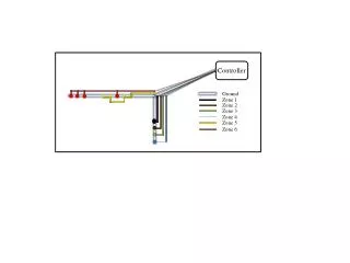
Microcontroller Logic (3) Addressing the Board Repeat for # of Rows/2 Obtain Grid Size (8 Col x 16 Rows) Repeat for # of Columns (0 / 1) Output1 Grid(Column, Row) Output2 Grid(Column, MaxRow-Row-1) (1…8) Load Images Into Flash ROM Call Clock Transition for Appropriate Output: Clock1 -> Out1 Clock2 -> Out2 Output Addr Bits (000…111) Address Data (0 / 1) TO CIRCUIT Clock 1 Clock 2
Original Signals From Microcontrollers Quick relay of image data Amplification? BJT LED Matrix PCB? Multiple rows of individual LEDs 8-bit Registers to store signal Necessity to load, but easily and cheaply implemented. Amplification Inverting Buffer LED Matrix Final layout on printed circuit board. Circuit Design Initial Design Final Design
Why? Much simpler to use Serial-In Parallel-Out registers Simultaneously drive 8 LED’s, smaller chip size compared to PIPO. Will they work? What Vcc is needed? What can it drive? (not powerful enough for LED’s) What can it read? Register Specifications Chip 74AC164 At 6V supply Vin(high-min) = 4.4 V Vin(low-max) = 1.6 V Vout(high-min) = 5.4 V Vout(low-max) = 0.6 V Isource(min) = -8.0 mA (not enough for LED) Good for use with Basic-X, but need something to drive LEDs 8-bit Registers
Signal Amplification • Chip 74AC540 – Octal Buffer/Line Driver with 3-State Outputs. • Similar to 74F240, 241, and 244, but chosen for layout (inputs opposite outputs). • Meets desired specifications • Vin(high-min) = 4.2 V • Vin(low-max) = 1.8 V (within output bounds of register) • Vout(high-min) = ~5.0 V • Vout(low-max) = 0.55 V • Output source/sink: 24 mA (enough for LED) • Why Inverting?
Why Inverting? • Inverting buffer turns on LED when register outputs High, off when register is Low, using a simple circuit. • LED circuit is designed to minimize the current but maintain a voltage across the LEDs. • LED turn on voltage ~1.7 V • Current falls within limits of buffer source/sink.
Circuit Design cont. • Need a method to address multiple registers. • Solution: DM74ALS138 • 3 to 8 Line Decoder/Demultiplexer • Vin(high-min) = 2 V • Vin(low-max) = 0.8 V • Vout(high-min) = 4 V • Vout(low-max) = 0.5 V • Use DMUX output as clock for each register. • Need to invert, register uses low-high clock transition, DMUX outputs remain High unless selected. • 74F04 Inverter
Circuit Design cont. • Need to design and test a suitable circuit for the LED array. • Controls to load the registers using the DMUX. • Get data to all the registers to display on the LEDs through the inverting buffer. • After choosing a final circuit, design a PCB to implement the circuit.
Data Loading Controls • DMUX to select register. • Output to each register used as a clock, inverted so that rising edges line up. • Using the DMUX enable allows a single clock to control an entire half. • Top (right) half has inverted address pins so that address (000) selects register 1 on both halves (simplifies software implementation)
Data Path • All registers share a common data input from the Basic-X. • Each register has its own clock from the DMUX, selected with the address bits. • Data is serially loaded into the register • 8-bit Serial Input, Parallel Output Registers. • Register outputs are run through an inverting buffer. • Allows more current to drive LEDs • Inverted so that LED reflects the bit in the register.
PCB Layout • Objective: Design a PCB to hold a large (16X8) array of LEDs and all the necessary chips. • Arrange loading controls and data path. • Circuit layout so that LEDs will be close together. • Challenging Design!
PCB Layout • Use Easytrax PCB software, have Parts Shop manufacture the board. • Need to Map • Register to Buffer tracks • Buffer to LED tracks • DMUX to Inverters to Register Control tracks • Control and Data tracks to the registers and DMUX • Power and Ground tracks to all chips. • Able to use two layer design with track width as narrow as 10 mil. (1 mil = 10-3 inches) • Design features for easy scalability. • Selectable Clock for DMUX control. • Connectors on both sides (top and bottom half) to pass all signals to next board.
PCB Layout • Due to arrangement on PCB, loading an image into the registers requires manipulation. • Top and bottom half of LEDs for each set of 8 registers. • Two columns of 4 belong to each register on half. • For Basic-X, the GUI generated text file is arranged so that the correct bit is loaded into the correct register.
Functional Tests GUI Microcontroller Circuit Proper Look and Feel Load External Files (Flash LEDS) Small PCB -Practice soldering of chips -Determine best layout, LED Positions -Discover nuances of PCB Proper Text File Generation Does the image display correctly? -Test image loading Can Development Board Buttons Be Used? LED I-V Characteristics 8 LED prototype on Protoboard: -Test functionality of Register and Buffer -Later test with Microcontroller (clock, data, and clear bits) Ongoing Compatibility Checks to Ensure That There Is Full Integration between GUI, Basic-X, and Circuit 3, 8 LED lines on Protoboard: -Test functionality of DMUX and Inverters -Later test with Microcontroller (address and clock bits)
Successes Design Worked! Learned Several New Skills: PCB Design Software & Layout Techniques Basic-X Microcontroller Language JAVA layered graphics Soldering Non-trivialities of circuit design Challenges Choosing a final circuit design Interfacing the different modular components - (Power) Soldering final circuit board Developing JAVA Interface Successes and Challenges
Additional Tests - Power Consumption 16 x 8 LED Matrix consumes 6 watts of power (max),
Possible Follow-up Projects: Create Wireless Link Between Microcontroller and GUI Interface to Create Remotely Located Sign Controller Scale-up Matrix to display larger images / text Replace Basic-X with a more sophisticated microprocessor to achieve faster scrolling (possible “animation”) Trim down design and use for possible ECE 249 MP / ECE 246 Final Project Recommendations