Download
1 / 61
620 likes | 814 Vues
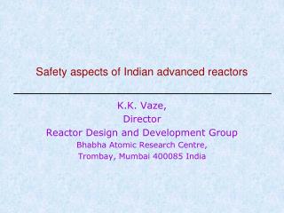
Safety aspects of Indian advanced reactors. K.K. Vaze, Director Reactor Design and Development Group Bhabha Atomic Research Centre, Trombay, Mumbai 400085 India. 1. Post Fukushima Scenario. Fukushima Accident.

E N D
Safety aspects of Indian advanced reactors K.K. Vaze, Director Reactor Design and Development Group Bhabha Atomic Research Centre, Trombay, Mumbai 400085 India 1
Fukushima Accident On March 11th, 2011, a gigantic earthquake with a magnitude 9 on the Richter scale shook Japan. The earthquake triggered a tsunami, which was exceptionally high, reached the Fukushima coast about one hour after the earthquake. All reactors in operation at Fukushima shut down automatically. While the offsite external power source was lost due to the earthquake, emergency diesel generators (EDG) started up properly Even though the earthquake was of a magnitude far greater than anticipated, there is today no evidence that it produced mechanical or structural damage which would have, in the absence of the tsunami, caused a severe accident. The seismic response analysis and the visual investigations conducted so far did not seem to show major damage to safety-related equipment.
Fukushima Accident - contd The majority of the damage was caused by the tsunami. At Fukushima Daiichi it caused complete loss of AC power, loss of ultimate heat sink and serious degradation of DC power sources. This led to the loss of decay heat removal at three NPP units, to severe reactor core damage, to the loss of containment integrity and to significant radioactive releases to the environment. In addition, the upper part of the fourth unit reactor building was destroyed by hydrogen explosion and the spent fuel pool structures of that unit suffered mechanical damages.
Some reassuring thoughts as far India is concerned • Huge earthquakes and huge tsunamis are not commonplace
Status of Seismicity – Indian NPPs • Criteria - No Active fault within 5 km Site Seismic Zone Narora IV Rawatbhata II Kakrapar III Tarapur III Jaitapur III Kaiga III Kalpakkam II Kudankulam II
Tsunamigenic locations for Indian coast TARAPUR KALPAKKAM ONLY FAR FIELD SOURCES KUDANKULAM TECTONIC PLATE BOUNDARIES 18 March 2011
How does this benefit us? Fukushima • Earthquake knocked out Class 4 supply • Tsunami knocked out other supplies India • EQ and tsunami don’t occur together • Ground motion due to an earthquake causing tsunami is negligible • Earthquakes causing significant ground motion do not cause tsunami • We get warning (~ 2 hrs)
Fukushima AccidentLessons Learnt Source: Prevention and Mitigation — Equal PrioritiesProf. Vladimir Asmolov, WANO President The key criterion of success: - recovery of power supply - water feed for the decay heat removal As prompt as possible! Availability of undamageable portable engineering means for power and water supply in the conditions of NPP isolation Accident prevention and accident mitigation: - implementation of design fundamental; - emergency preparation; - Severe Accident management.
Source: Prevention and Mitigation — Equal PrioritiesProf. Vladimir Asmolov, WANO President
Securing energy for India’s future is a major challenge World OECD Non-OECD India India (developing world) of our dream Population (billion) 6.7 1.18 5.52 1.2 1.6 (stabilised) Annual av. per ~2800 ~9000 ~1500 ~780 5000 capita Electricity (kWh) Annual Electricity Generation 18.8 10.6 8.2 0.835 8.0 (trillion kWh) Carbon-di-oxide Emission 30 13 17 1.8 ? (billion tons/yr) • India alone would need around 40% of present global electricity generation to be added to reach average 5000 kWh per capita electricity generation Dr. Kakodkar “Atoms for Prosperity
Global climate change is an immediate threat 1979 2003 Comparison of sea-ice from 1979 and 2003. • Just ten years from now, greenhouse emissions from developing nations will equal the emissions from the countries we now call developed. After that, emissions from the developing world will be the major driver of global climate change. • While energy conservation, windmills, and solar panels may help, we cannot hope to rely on such measures alone to meet our world’s expanding appetite for more energy. John Ritch, Director General of the World Nuclear Association, 15th Pacific Basin Nuclear Conference, Sydney, 15-20 Oct. 2006 Source:http://www.nasa.gov/centers/goddard/news/topstory/2003/1023esuice.html
CNS Extraordinary Meeting Summary Report The displacement of people and the land contamination after the Fukushima Daiichi accident calls for all national regulators to identify provisions to prevent and mitigate the potential for severe accidents with off-site consequences. Nuclear power plants should be designed, constructed and operated with the objectives of preventing accidents and, should an accident occur, mitigating its effects and avoiding off-site contamination. The Contracting Parties also noted that regulatory authorities should ensure that these objectives are applied in order to identify and implement appropriate safety improvements at existing plants.
Dr. Kakodkar • An essential goal for nuclear safety is “Never Again” should there be any significant off site emergency • Dual level design basis • Design Basis • Risk Lowered to an acceptable level • No impact in public domain • Extreme Event • Maximum potential • No significant off-site emergency • Extra margin between design and ultimate load capacity should be sufficient to cope with this
Can the nuclear community set for itself an ambitious goal to meet the challenge of the numbers? “Four decades from now, in any country of the world, it should be possible to start replacing fossil fuelled power plants, at the same urban or semi-urban site where these are located, with advanced NPPs that would, more economically, deliver at least twice the power that was being produced by the replaced plants” R.K. Sinha, “The IAEA’s Contribution to the Peaceful Use of Nuclear Power”, Nuclear Power Newsletter, Vol. 3, No. 3, Special Issue, Sept. 2006
Level of safety goals increases with multi-fold increase in deployment of nuclear reactors Special Siting Criteria, Risk approach Special Siting Criteria (may/may not); CDF, LERF Siting criteria Dose Criteria Safety Goals Advanced future Reactor Systems Advanced reactors under construction Reactors under operation (existing technology) Number of reactors in operation 19
Achievement of safety goals through enhanced levels of Defence-In-Depth • Strategy for safety measures and features of nuclear installations is two-fold: • To prevent accidents • Preventing the degradation of plant status and performance • If prevention fails, limit their potential consequences and prevent any evolution to further serious conditions Monitored Process Parameter
Passive and Inherent Safety Features are Instrumental in Meeting New Safety Criteria • The conventional reactors or so called “Traditional ones” have seen an extensive use of “active” engineering safety systems for reactor control and protection in the past. • These systems have certain potential concerning termination of events or accidents that are effectively coped with by a protective system limited by the reliability of the active safety systems or prompt operator actions. • Since the reliability of active systems can not be improved above a threshold and that of the operator’s action is debatable, there is growing concern about the safety of such plants due to the large uncertainty involved in Probabilistic Safety Analysis (PSA) particularly in analyzing human faults. • In view of this, a desirable goal for the safety characteristics of an innovative reactor is that its primary defence against any serious accidents is achieved through its design features preventing the occurrence of such accidents without depending either on the operator’s action or the active systems. • That means, the plant can be designed with adequate passive and inherent safety features to provide protection for any event that may lead to a serious accident. • Such robustness in design contributes to a significant reduction in the conditional probability of severe accident scenarios arising out of initiating events of internal and external origin.
Example of Applications Passive Systems and Inherent Safety Features in Defence-In-Depth in AHWR
The Indian Advanced Heavy Water Reactor (AHWR-Pu) AHWR is a 300 MWe vertical pressure tube type, boiling light water cooled and heavy water moderated reactor using 233U-Th MOX and Pu-Th MOX fuel. Major design objectives • 65% of power from Th • Several passive features • 7 days grace period • No radiological impact • Passive shutdown system to address insider threat scenarios. • Design life of 100 years. • Easily replaceable coolant channels. Top Tie Plate Displacer Rod Water Tube Fuel Pin Bottom Tie Plate • Design validation through extensive experimental programme. • Pre-licensing safety appraisal by AERB • Site selection in progress. • Detailed engineering consultancy in progress AHWR-Pu is a Technology demonstrator for the closed thorium fuel cycle AHWR Fuel assembly AHWR-LEU extends the AHWR technologies with LEU-Th MOX Fuel for the global market
AHWR incorporates several technolological solutions to a higher level of safety and security against both internal and external threats No unacceptable radiological impact outside the plant boundary with Failure of all active systems, and Failure of external infrastructure to provide coolant, power and other services, and Malevolent acts by an insider, one of the consequences of which is the failure of instrumentation signal initiated shutdown actions, and Inability of plant operators to manage the events and their consequences, for a significantly long time. Control room and auxiliary systems Instrumentation & control signals Control and S/D systems Pneumatic supply Turbine Electrical power (Class 1 to 4) Core Condenser Pump External events Malevolent act Ultimate heat sink (Cooling tower or sea)
Some important passive safety features of AHWR –1/4 Heat removal from core under both normal full power operating condition as well as shutdown condition is by natural circulation of coolant.
Some important passive safety features of AHWR –2/4 (Th-Pu) MOX Fuel pins (Th-233U) MOX Fuel pins Central Tube for ECCS water AHWR FUEL CLUSTER Passive Containment Cooling Passive Containment isolation Passive injection of cooling water, initially from accumulator and later from the overhead GDWP, directly into fuel cluster.
Some important passive safety features of AHWR –3/4 Passive Poison Injection in moderator during overpressure transient Passive Poison Injection System actuates during very low probability event of failure of wired shutdown systems (SDS#1 & SDS#2) and non-availability of Main condenser
Some important passive safety features of AHWR –4/4 Use of moderator as heat sink Water in calandria vault Flooding of reactor cavity following LOCA
Fukushima and AHWR AHWR has been assessed for TMI as well as Chernobyl type of accidents Critics comments: It is easy to become wise after the event (TMI, Chernobyl) Fukushima type event (Extended SBO) was anticipated even before it happened Practically no change required in AHWR design to meet Fukushima event GDWP and passive systems adequate to cater to the extended SBO No impact in public domain, No need of evacuation No need of exclusion zone, sterilized zone
Prolonged Station Black Out in AHWR Decay heat removal by Isolation Condensers • A strong earthquake with/without Tsunami causing prolonged SBO for several days. Reactor tripped on seismic signal. • Gravity Driven Water Pool is intact. • Heat is removed by Isolation Condensers • GDWP water removes decay heat for ~110 days with periodic containment venting allowed after 10 days.
Level 1 DID: Elimination of the hazard of loss of coolant flow: Heat removal from the core under both normal full power operating condition as well as shutdown condition is by natural circulation of coolant. Reduction of the extent of overpower transient: Slightly negative void co-efficient of reactivity. Low core power density. Negative fuel temperature coefficient of reactivity. Low excess reactivity Passive Systems in Defense-In-Depth of AHWR
Passive Systems in Defense-In-Depth of AHWR (Contd.) • Level 2: Control of abnormal operation and detection of failure • An increased reliability of the control system achieved with the use of high reliability digital control using advanced information technology. • Increased operator reliability achieved with the use of advanced displays and diagnostics using artificial intelligence and expert systems. • Large coolant inventory in the main coolant system. • Level 3: Control of accidents within the design basis • Increased reliability of the ECC system, achieved through passive injection of cooling water directly into a fuel cluster through four independent parallel trains. • Increased reliability of a shutdown, achieved by providing two independent shutdown systems. Further enhanced reliability of the shutdown, achieved by providing a passive shutdown device • Increased reliability of decay heat removal, achieved through a passive decay heat removal system, which transfers the decay heat to GDWP by natural circulation. • Large inventory of water inside the containment (about 8000 m3 of water in the GDWP) provides a prolonged core cooling meeting the requirement of grace period.
Passive Systems in Defense-In-Depth of AHWR (Contd.) • Level 4: Control of severe plant conditions, including prevention of accident progression and mitigation of consequences of severe accidents • Use of moderator as heat sink. • Presence of water in the calandria vault • Flooding of reactor cavity following a LOCA. • Level 5: Mitigation of radiological consequences of significant release of radioactive materials • The following features help in passively bringing down the containment pressure and eliminates any releases from the containment following a large break LOCA: • Double containment; • Passive containment isolation • Core catcher • Filtered vent
Peak Clad Temp v/s frequency of occurrence – a quantitative probabilistic safety criteria
Core Damage Frequency Per Year AHWR ~ 1x10⁻⁸ Ref: Lecture on Near Term Advanced Nuclear Reactors and Related MIT Research, by Prof. Jacopo Buongiorno, MIT, USA, June 16, 2006.
Incorporation of Hard vent • Hard Vent system is designed to prevent the over pressurization of the containment beyond design pressure occurring due to failure of multiple safety systems because of an extreme event such as prolonged SBO with non-availability of GDWP water or large seismic event causing cracks in GDWP along with LOCA. • Also retains the radio-activity in the scrubber and minimize activity release beyond the containment boundary. • Scrubber tank contains water + NaOH solution (ph = 8.5). • NaOH combines with Iodine whereas Cs which is in form of CsI, CsOH, CsO2, Cs2CO3 is soluble in water. • A 4 inch Dia pipe is provided at the top of primary containment for venting, which will be connected to scrubber tank. To Stack From Containment 3 I2 + 6 NaOH = 3 H2O +5 NaI + NaIO3
Passive Autocatalytic ReCombiner System (PARCS) • Postulated Accidents DBA:Single failure (LB LOCA): No hydrogen generation BDBA: Multiple failure (LBLOCA and non-availability of Wired Shutdown System) ~ 30 kg in 300 s. Prolonged SBO + non-availability of GDWP ~ 450 Kg in 2 hr starting after 40hrs of transient (~5000 m3 at ambient) • Peak H2 generation rate ~ 0.3 kg/s Recombination rate ~ 0.1 kg/hr/m2 (for 2 - 4% H2 conc.) Overall box size : 1000 x 400 x 1000 (L X B X H) (8.29 m2 of Catalyst Deposited area) Estimated Conversion rate : 0.83 kg/hr No. of Recombiners for one Plant ~ 100 (Total Conversion Rate = 83 kg/hr) The released hydrogen will be combined by Passive Autocatalytic Recombiners (PARCS) located at several locations in the containment designed in such a way to reduce the hydrogen concentration in the containment below the flammability limits. Experiments are being carried out for demonstration of hydrogen removal using PARCS
Sacrificial concrete layer mixes with the melt, reduces its temperature, solidus temperature (typically from 2800oC to 1500oC) and helps in spreading the melt over large surface area Poison added in sacrificial concrete prevents recriticality High porosity concrete layer below the sacrificial concrete helps in flooding water from below Riser tubes inject water within the melt-concrete mixture The downcomers supply water to the water pool from GDWP passively Design of Core Catcher High porosity concrete (300 mm depth) Sacrificial Concrete (300 mm depth) Riser Tubes ( 100mm) 7.4 m Water pool (500 mm depth) Structure of core catcher Water from GDWP Sacrificial concrete composition Design objective of the core catcher • Retention of the melt in the cavity • Quenching it within 30 minutes • Stabilize it for substantial period of time (several days) 39
Indian High Temperature Reactor Programme Status: Design of most of the systems worked out. Fuel and materials under development. Experimental facilities for thermal hydraulics setup. Facilities for design validation are under design. • Compact High Temperature Reactor (CHTR)- Technology Demonstrator • 100 kWth, 1000 °C,TRISO coated particle fuel • Several passive systems for reactor heat removal • Prolonged operation without refuelling Status: Optimisation of reactor physics and thermal hydraulics design, selection of salt and structural materials in progress. Experimental facilities for molten salt based thermal hydraulics and material compatibility studies set-up. • Innovative High Temperature Reactor for Hydrogen Production (IHTR) • 600 MWth , 1000 °C, TRISO coated particle fuel • Small power version for demonstration of technologies • Active & passive systems for control & cooling • On-line refuelling • Indian Molten Salt Breeder Reactor (MSBR) • Large power, moderate temperature, and based on 233U-Th fuel cycle • Small power version for demonstration of technologies • Emphasis on passive systems for reactor heat removal under all scenarios and reactor conditions Status: Initial studies being carried out for conceptual design 41
Technology for fuel kernel by sol-gel technique is well established – Focus is on technologies for TRISO coating and fuel compact OPyC SiC Zirconia IPyC Buffer PyC X-ray radiographic image of TRISO particle with Zirconia kernel Radiograph and tomograph of fuel compact made by different technique SEM images of particle with Nat. UO2 kernel Fuel Compacts Initial trials with zirconia kernels completed Fabrication trials of TRISO fuel using natural UO2 kernel carried out Fuel compact prepared by two different techniques High packing density (45-50%) achieved
Fabrication of C/C composite tubes and coating with SiC High Temperature Fluidized bed Coater (Inset shows fluidized bed distributor assembly) Induction heating system Fluidised bed based SiC coating method developed Cooling tower Sample with graphite fixtures and graphite susceptor • High density C-C composite fuel tube samples fabricated in collaboration with National Physical Laboratory, New Delhi • Pre-form was made using high strength carbon fibers • Pre-form subjected to multiple cycles of resin impregnation and hot iso-static pressing with intermediate machining cycles Arrotameter Machining trials of graphite components (AFD) Fluidized Bed Distributor Heated graphite being dipped in fluidized bed
Thermal hydraulic studies for liquid metal (Pb-Bi) Liquid Metal Loop (2009) • Major areas of development • Analytical studies and development of computer codes • Liquid metal loop for experimental studies • Loop at 550 °C in operation since 2009 • Loop at 1000 °C under commissioning • Steady state and transient experiments carried out • In-house developed code validated • Experimental and analytical studies for freezing and de-freezing of coolant • Test bed for development of instrumentation –level probes, oxygen sensor, EM pump and flowmeters YSZ based oxygen sensor Comparison of steady state correlation [Vijayan, 2002] with experimental data 44
Sufficient time margin before shutdown or passive alternate heat removal system needs to act • Case-1 • 250% step increase in power • LOCA • No heat sink • Case-2 • Similar to case-1, but with a 300% “spike” in power before stabilizing at 250% ~58 min ~40 min Sufficient time available to activate primary and/or secondary shutdown system, or passive gas-gap filling system
Negligible rise in peak temperatures after shutdown due to decay heat Minimum temperatures well above freezing point of coolant even after 1 hour
Innovative High Temperature Reactor (IHTR) for commercial hydrogen production • 600 MWth, 1000 °C, TRISO coated particle fuel • Pebble bed reactor concept with molten salt coolant • Natural circulation of coolant for reactor heat removal under normal operation • Current focus on development: • Reactor physics and thermal hydraulic designs – Optimisation • Thermal and stress analysis • Code development for simulating pebble motion • Experimental set-up for tracing path of pebbles using radio-tracer technology • Pebble feeding and removal systems TRISO coated particle fuel Pebble • Hydrogen: 80,000 Nm3 /hr • Electricity: 18 MWe, Water: 375 m3/hr • No. of pebbles in the annular core ~150000 • Packing fraction of pebbles ~60% • Packing fraction of TRISO particles ~ 8.6 % • 233U Requirement 7.3 %
Thermal hydraulic studies and material compatibility studies for molten salt coolant • Major areas of development • Analytical studies and development of computer codes • Molten salt natural circulation loop for experimental studies • Molten fluoride salt corrosion facility using FLiNaK • Experiments being carried out upto 750 °C mainly on Inconel materials Molten salt loop Molten salt corrosion test facility 48
Design features of Indian HTRs leading to inherent safety • TRISO coated fuel particles: Retention of fission products up to 1600 °C • High thermal inertia of ceramic core and low power density • Sufficient margin between reactor operation and boiling point of the coolant • Negative temperature coefficient of the core and coolant • Natural circulation of liquid metal / molten salt coolant in single phase • Low pressure of the system • Passive removal of heat under normal operation and postulated accident scenarios • High temperature heat pipe for CHTR • Chemical inertness of the lead based coolant with air/water
Molten Salt Breeder Reactor (MSBR) This concept is attractive to India because of large thorium reserves and possibility of breeding 233U in thermal spectrum – For the third stage of Indian Nuclear Power Programme