
Atmega32 Architectural Overview
E N D
Presentation Transcript
Atmega32 Architectural Overview CS-280 Dr. Mark L. Hornick
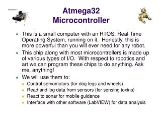
Atmel Atmega32 highlights An 8-bit microcontroller featuring: • 3 separate on-chip memories (Harvard architecture) • 2KB SRAM (for data – volatile; data lost on power off) • 1KB EEPROM (for persistent data storage – holds data after power off) • 32KB Flash (organized as 16K of 16-bit words for persistent program code) • Native data size is 1 byte (SRAM and EEPROM) • 16-bit data addressing • Up to 64 KB (216 bytes) of data memory can be accessed • 8-pin I/O ports named A, B, C, and D, program-configurable as: • Digital input (for reading discrete external signals on each pin (0v or 5v) as data values 0 or 1) • Digital output (for writing binary data values as discrete output signals (0v or 5v) • Analog input (for reading continuous external signals (0v-5v) as data values) • Serial/Parallel (for reading or writing streams of bytes) • Pulse accumulator (for counting #changes of external signals) CS-280 Dr. Mark L. Hornick
Inside an IC package CS-280 Dr. Mark L. Hornick
Inside an IC package CS-280 Dr. Mark L. Hornick
Atmel Atmega32 • Central Processing Unit • Arithmetic Logic Unit (ALU) performs the actual arithmetic, logical, and bit-functions • Memory – SRAM, EEPROM, Flash • Clock circuit – internal/external • I/O – Input/Output; video, serial, parallel, USB, SCSI, etc. CS-280 Dr. Mark L. Hornick
CS-280 Dr. Mark L. Hornick
3 Separate on-chip memories • Programs are stored in 32KB Program Flash • Persistent: contents are retained when power is off (non-volatile) • Organized as 2-byte words; individual program instructions generally take 2 bytes, but some take 4 bytes • Each word has a unique 16-bit address (0-0x3FFF) • Fast to read; slow to write • Can only write entire “blocks” of memory at a time • 2KB SRAM for temporary data storage • Contents are lost when power is shut off (volatile) • Fast read and write • Native data size is 8 bits (1 byte) • Each byte has a unique 16-bit address (0x60-0x85F) • 1KB EEPROM for persistent data storage • Contents are retained when power is off (non-volatile) • Fast read; slow write • Native data size is 8 bits (1 byte) • Each byte has a unique 16-bit address CS-280 Dr. Mark L. Hornick
Flash Program Memory layout • There are 32KB of program memory (Flash memory) • Organized as 16K 2-byte words • Because program instructions are either 2 (common) or 4 (less common) bytes long • Each word (not byte) in Flash memory has a unique address • Beginning address $0000 • Ending address $3FFF • Some Flash memory is reserved or protected • First 42 words (reserved) • Last NNN words (protected) Reset and interrupt vector section42 words (84 bytes) $002A Your programs go here! $3C00 Number of bytes depends onuser-definable configuration CS-280 Dr. Mark L. Hornick
Data Main Memory CPU +Program Most general-purpose microprocessors (like in your PC) use a von Neumann Architecture • Data and instructions are both stored in the same main memory • The content of any part of memory is addressable by location without regard to what is stored in that location – program or data • Instructions are executed sequentially. In case of accidental or intentional programming errors, data can be executed – a common attack used by viruses Microcontroller Components
The Atmega32 design is based on a Harvard Architecture: • Assigns data and program instructions to different memory spaces. • Program data occupies a different and separate memory from the program itself. • Each memory space has a separate bus, allowing: • Different timing, size, and structure for program instructions and data • Concurrent access to data and instructions (increases speed) • Clear partitioning of data and instructions (better security) • Drawback: Harder to program Microcontroller Components
The machine-instruction is executed by the Central Processing Unit • When the device is powered-on, the Program Counter is set to 0. • The instruction at the location in Flash Memory at the address indicated by the Program Counter is fetched and placed in the Instruction Register • The opcode and operands within the instruction are extracted by the Instruction Decoder • The control lines from the I.D. activate the particular circuitry within the ALU that is capable of processing that particular opcode. The ALU executes the instruction. • The Program Counter is automatically incremented and the cycle repeats. CS-280 Dr. Mark L. Hornick
Instruction execution timing CS-280 Dr. Mark L. Hornick
An Assembler converts human-readable assembly language instructions into machine-executable instruction that are stored in Program Flash Memory Consider the assembly language instructionadd rD, rS • add is a reserved assembly language instruction mnemonic • rS and rD are operands that refer to source and destination general-purpose registers • This instruction adds the contents of register rS to register rD, storing the sum in rD. • Example: Substitute any actual register (R0-R31) for rS and rD : add r20, r5 • case is not important; the instruction can also be written as ADD R20, R5 CS-280 Dr. Mark L. Hornick
Let’s consider the case of how the ADD instruction is represented as a machine-executable instruction Example: ADD R20, R5 • A 16-bit machine instruction is generated (by the assembler) for this particular case • Machine instructions consist of an numeric opcode and operands • The opcode in this case is 000011 (3) • Each register operand is represented by 5 bits • 5 bits are required to represent all possible register values from 0-31 • ddddd represent the 5 bits that represent the destination register value (20) • rrrrr represent the 5 bits that represent the source register value (5) 0000 11rd dddd rrrr Note: The bits ddddd and rrrrr are “split” in this instruction add r20, r5 is assembled to: 0000 1101 0100 0101 This 16-bit binary word can be expressed in hexadecimal as 0x450d (with the “high” byte being rightmost) CS-280 Dr. Mark L. Hornick
The ALU can only directly operate on data that has been fetched into the Registers. It cannot directly operate on SRAM or EEPROM data. In the assembly language instructionadd r20, r5 • We (the programmer) must first load some values into these registers. Once way of doing this is with the following instructions: ldi r20, 2 ; load value 2 into r20 lds r5, 0x60 ; load value at SRAM addr 0x60 into r5 add r20, r5 ; add them; result is in r20 • Following the add, we normally store the sum (the value in r20) someplace (like in SRAM). More on how to do that later…how would you guess it might work? CS-280 Dr. Mark L. Hornick
General Purpose Registers • There are 32 8-bit GP registers R0-R31 • Used as accumulators – for most math and logic • X, Y, Z are 16-bit registers that overlap R26-R31 • Used as address pointers • Or to contain larger values (>255) CS-280 Dr. Mark L. Hornick
Special-purpose Registers can also be operated upon directly by the ALU (with certain specific instructions) • Stack pointer (SP, 16-bit) • Stores return address of subroutine/interrupt calls • Storing temporary dataand local variables • Program counter (PC, 16-bit) • Holds address of next program instruction to be loaded and executed • Automatically incremented when the ALU executes an instruction • Status Register (SREG, 8-bit) • Contains information of result of most recent ALU operation CS-280 Dr. Mark L. Hornick
Yet another Development System: AVRStudio • Editor (for writing programs in assembly language) • Assembler (like a compiler, but much simpler) • Program downloader (loads the assembled code to the Atmega32) • Debugger • Monitor – (remote debugging on the actual Atmega32) • Simulator – (local dubugging using a simulation of the running Atmega32) CS-280 Dr. Mark L. Hornick