Flight Readiness Review
Flight Readiness Review. West Point-Beemer’s SLI Vehicle and Payload Experiment Criteria. The Test Flight:. Length: 87" Diameter: 5.54" Weight: 19.5lbs Motor: AMW K975 Electronics: ARTS 2.0, MAWD, Beeline GPS, Beeline classic (for tracking the nose)

Flight Readiness Review
E N D
Presentation Transcript
Flight Readiness Review West Point-Beemer’s SLI Vehicle and Payload Experiment Criteria
The Test Flight: • Length: 87" • Diameter: 5.54" • Weight: 19.5lbs • Motor: AMW K975 • Electronics: ARTS 2.0, MAWD, Beeline GPS, Beeline classic (for tracking the nose) • Deployment: Pilot/Drouge at Apogee, R14 at 750' via Defy Gravity Tether. • Max G-force:15.03 • Max Velocity: 812f ps , 553mph • Max Baro Alt (ARTS): 6165' • Max Baro Alt (MAWD): 6100' • Max Acc Alt (ARTS): 6188' • Time to Apogee: 18.25 sec • Descent rate under drogue : 61.0 fps • Descent rate under main : 16.9 fps
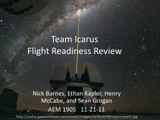
Liftoff All Test Launch Pictures by Thomas Kernes, used with permission
Success! • Altitude much higher than planned, camera and remote launcher can now be added • All systems performed well • Science payload on board but not recording, more tests (ground) will be done on that
Lessons learned • If you think it will take an hour to prep, it will take 3 • Do more testing to make sure the Tether fires off the first match and doesn’t wait for the second • Drill vent holes to allow main bag to slide out easier • Sample GPS data more often • Take better pictures ourselves • Assemble the motor right the first time • Don’t always listen to what people say (Kevin on motor cleaning….) • A single Pyrodex pellet does not insure instant ignition. 3 should be plenty and still safe • Sand centering rings to make tubes easier to slide
Proper Use of Structural Elements • Cardboard tubes-commonly used • Plywood fins-strong and common • Plywood structure-uncommon, but plenty strong and easy to work with • Wood glue-best bonding agent for wood to wood and wood to cardboard
Assembly Strengths, Load Paths • Interlocking fin unit is inherently strong and automatically aligned when assembled • Load Paths-Motor thrust ring-> Body tube-> Nose Cone • Load Paths-Top of motor-> truss structure-> Electronics bay-> Body tubes-> nose cone
Motor Retention • 3/8” Threaded Rod that the motor is screwed into when assembled
Integrity of Design • Flight test proves that the design works, or at least did once, so far. In general, structurally it is strong enough for all transport, prep and flight loads.
Relation of approach to workmanship and mission success • Taking care to ensure mission success will be in mind at all times during construction, testing, prepping and flying. Sloppy jobs and rushed work will not be accepted and will be redone until it is acceptable to achieve mission success. The design of the rocket itself makes sloppy work more work than good work.
Recovery • Rocketman R14 Main parachute • Defy Gravity Tether used to hold main in until 700’ • Man-rated pilot/drogue to pull main bag out • 3 gram 4fg powder charge to pop nose at apogee
Failure Analysis of Recovery(parts not already covered previously)
Mission Performance Criteria • 1 mile AGL • Recovered within field • No damage
Simulations • Will use actual vehicle and weather data in Huntsville to determine final weight necessary for a 1 mile flight. • Data from test flight will be used in simulations
Safety And Environment • Andrew is our safety officer. He has experience in risk mitigation in complex, high risk high power rocket construction and flight. All participants will be required to show the necessary knowledge of our safety plan.
Prevention of Inadvertent Activation of Remote Control Devices • Devices will utilize shunts and switches that break the circuit to prevent current flowing to igniters when device isn’t armed. • Devices will not be able to be actuated unless a unique 60ms code is received. • 9 x 10 ^-9 % chance of inadvertent activation by a non involved part
Personal HazardsContinued • Always wear safety glasses when dealing with rocket parts containing small hardware or pyrotechnic charges. • Never look down a tube with live pyrotechnic charges in it. • Always point rocket and pyrotechnic charges away from body and other people. • Avoid carrying devices that have live electrical contacts (radios, cell phones, etc.) while prepping live pyrotechnic charges. • Never arm electronics when rocket isn’t on pad unless the area has been cleared and everyone knows that pyrotechnic continuity checks are being done. • Always follow the NAR/TRA safety codes. • Always follow all applicable local, state and national laws and regulations. • Only the Level 2 certified mentor may handle the motor (CPSC regulations). • Do not allow smoking or open flames within 25 feet of the motor or pyrotechnics. • Avoid horseplay and idle conversation, focus on properly completing the task at hand. • Make sure the checklist is followed and all steps are completed properly in a though, workmanlike manner to assure mission success. • Since the motor for the flight utilizes snap rings to retain the ends of the motor, care must be taken when installing and removing snap rings. Snap rings can be sent flying at high speeds in unpredictable directions even if reasonable care is being taken, thus, all personnel within 25 feet of a snap ring installation or removal procedure will be required to wear safety glasses or move out of the area and keep eyes turned away from motor.
Environmental Concerns • All waste materials will be disposed of using proper trash receptacles, biodegradable and flame resistant recovery wadding will be used. Practice launches will only occur with local fire department permission if dry grass conditions exist. Bureau of Land Management regulations will be followed when doing test launches on BLM land. Solid rocket motor manufacture’s instructions will be followed when disposing of any rocket motor parts. Consideration of environmental ramifications will be made regarding applicable activities.
Payload integration • The electronics/payload bay is specifically designed for easy integration of the payload and deployment electronics. The data collection device will be simply bolted to one of the 4 trusses that span the length of the payload bay. The 9v battery that it will run on will also be mounted with zip-ties to a truss. The data collection tubes will slide in precision cut holes in the three rings inside the bulkhead. To slide them in, on of the bulkheads on either end of the electronics bay will be removed by removing the U-bolt on that end. This will expose the holes that the tubes slide into, they will then be slid in, secured with rings of masking tape to prevent them from sliding and the bulkhead and eye-bolt will be replaced.
Interface • The final outside diameter of the data collection tubes has not been finally determined at this point; however it is known that it will be below 1.5”. 4 1.5” holes will easily fit in the electronics bay as shown in the picture at the beginning of this report. The diameter of the holes in the final bay will be determined by using a caliper to measure the O.D. of the data collection tubes and put that value in AutoCAD so that the parts can be cut out accurately in the water cutting machine.
Integrity • As with the rest of the design, plywood of suitable strength will be used for supporting elements. This is done due to the strength, price, ease of use and common availability of plywood.
Launch Procedures • Checklists • Recovery • Pack Deployment bag before departure • Make ejection charges • Wire ejection charges to electronics • Set up Tether • Attach Tether charges to electronics • Attach main harness to eye-bolt • Install body tubes • Feed charges through tubes • Attach main parachute to shock cord • Install Main • Attach Tether to retention loop and nose shock cord • Attach pilot, Nomex pads and nose to nose shock cord • Install Beeline tracker in nose • Install cords • Install Nose • Tape nose on with 6 pieces of ½” masking tape
Launch Procedures (continued) • Motor Prep • Install O-ring on nozzle • Install nozzle • Install steel washer and snap ring (CAREFULLY!) • Install liner • Drop first 5 grains • Install Pyrodex boost charge in top grain (to be lit with an e-match) • Install top grain • Install tracking smoke • Put O-ring on forward bulkhead • Install forward bulkhead • Install final snap ring (CAREFULLY!) • Slide motor in rocket • Rotate to retain
Launch Procedures (Continued) • Set up on launcher • Slide onto rail • Raise rail upright • Arm MAWD • Arm Data recorder • Arm ARTS • Pose for pictures • Arm remote launcher • Install igniter • Straiten leads • Push to top of motor • Attach to remote launcher • Retreat to launch area • 1.1.4.1 Alert RSO/LCO of launch readiness • 1.1.4.2 Start Continuity check procedures • 1.1.4.3 Arm Vehicle • 1.1.4.4 Countdown from 5 • 1.1.4.5 Launch
Troubleshooting • The most likely cause of a launch failure is either a bad electric match, an improperly installed electric match or a problem with interference with the remote launcher. In the event that the electric match lights but fails to ignite the motor, replace the match and start again with igniter installation In the event that the match does not fire, replace the match and attach it to a standard wire controller and proceed with standard set up
Post flight inspection • Post flight inspection: • -Confirm all charges have fired • -Disarm/Safe electronics • -Detach main parachute, wrap lines into rocket and place nosecone back on • -Walk or drive back to prep area • -Remove tubes and download data from the data recorder, ARTS, MAWD and Beeline GPS tracker • -Clean motor • -Pack up for return trip
Remote Frequencies • -Beeline tracker 444.5 Mhz • Beeline GPS 434.5 Mhz • Remote Launcher 433.92 Mhz • Video camera 2.4 Ghz
Failure modes and hazards of launch: • The Tether requires care to not break the match heads, extra matches should be available incase of breakage. Snap rings are dangerous if they fly out when improperly installed. Care to avoid injury will be taken. Live motors and charges are dangerous, limit numbers of people will be allowed when igniters are installed in motors or charges are armed.
Payload • The Ideal gas law is fundamental to science. This will be a test of the gas law through a test of gasses in confined tubes during launch. We know what they should do, this is a test to if they will. Our Science has been in figuring out how to do this. We have had to go through different test and methods to arrive at a plan that will work for us. He feel that we have been significantly challenged in this part of the project, as we are now on plan D for our payload.
We had originally planed to confine the gas and let the expansion from altitude pressure decrease push a syringe attached to a sliding potentiometer. We tried this with a small and medium sized syringe and found that it would not move the plunger well enough to be reliable. From there we moved to our plan C. We would use a strain gauge on a flexible diaphragm at the end of our gas sample tubes. This device would have to be calibrated for pressure to resistance ratios, and would be testing the ideal gas law (PV=nRt) by changing pressure as our variable instead of changing volume from plans A and B. Strain gauges were ordered and tested. We could not get reliable results. We went back to syringes and tried a larger size. We were getting results that perhaps would work when we found in an electronics catalog a pressure sensor in the range that we needed. Freescale semiconductors produced a temperature compensated differential pressure sensor that operated in the 0 to 10 psi range outputting a 0 to 5 volt scale. The company cooperated and sent us 4 for evaluation.
Experimental Design of Payload • We feel that we have gone through a great deal of engineering in getting this to record the data we need. We have progressed to plan D to get the job done. We feel that our research has lead us to the most reliable and accurate method for data collection. Our calculations show that we should see about a 5 psi change in pressure or something in the 50 pa pressure range. With the PV=nRT equation, volume will be constant. We will calculate what the pressure should be at attitude and compare that to the pressure differences that we get from our confined gasses. Main steps for preparation: Clear data recorder of any old data Confirm new battery for recorder Attach recorder to tube sensors Confirm tubes at ambient pressure with a valve test Set the break wire on the data recorder Data recorder, battery, and all sensors will be secured to the rocket to withstand launch forces. The data recorder has been designed for the rigors of launch. Each of the tubes must be designed for launch forces also. Care must be taken in each step of payload construction to meet the best needs of payload success.
Assembly of Payload • The design of a custom data recording circuit has simplified our work significantly. When we located the needed pressure sensor, that completed the integration of our design. • All parts will be zip tied to the plywood structure of the rocket. The tubes will be integrated into the bulkheads of the rocket. These design ideas will insure reliability and success. • Each part will be inspected by other members of the team to insure quality construction. This will be cross checked by the mentors
Concerns: • Electric matches for the Tether must be small. Oxrals won’t work, M-techs should, Daveyfires will be close. What brand will be used down there and is it possible to get a different type shipped? • Igniters-we are comfortable with a Pyrodex pellet or two and an electric match. Will we need to buy a box of pellets or will another form of a fast action igniter be provided that NASA would prefer more? • In order to properly size boxes to carry the rocket on the airplane, the airline will need to be contacted. What airline will be used so we can contact them soon? • Will the rockets be available for prep the two or three nights before in the hotel? We wouldn’t need any matches or motors, but getting electronics worked on and that kind of stuff would be really nice.