Production Readiness Review
Production Readiness Review. E. Ladygin Joint Institute for Nuclear Research, Dubna, Russia L. Kurchaninov Max-Planck-Institut für Physik, Munich, Germany. Tower Driver Board for the ATLAS Hadronic End-Cap and Forward Calorimeters. 1. Design review and follow-up.

Production Readiness Review
E N D
Presentation Transcript
Production Readiness Review E. Ladygin Joint Institute for Nuclear Research, Dubna, Russia L. Kurchaninov Max-Planck-Institut für Physik, Munich, Germany Tower Driver Board for the ATLAS Hadronic End-Cap and Forward Calorimeters E.Ladygin, L.Kurchaninov
1. Design review and follow-up TDB has been reviewed in June 2002 with following comments: • All power inputs are to be fused, with large safety factors (at least a factor of 2) for the current limits. The fuse should be soldered to the board. • The usage of voltage regulators is required in all front-end boards. In particular, the TDB circuits biased with +5.2V and –5.2V produced from external +7.0V and –7.0V respectively. • Voltages on the power lines of the LARG front-end crate fixed to +7.0V (line 4) and -7.0V (line 9). The TDB has to be modified to use these values. • The TDB will not employ a cooling plate in order to have adequate room on the front panel for the six cable connectors. The resulting off-loading of power to neighbouring boards in the crate has to be measured. • The Level 1 trigger cables have line impedance of 88W, this value should be used when considering resistance values for back termination of the cable. E.Ladygin, L.Kurchaninov
1. Design review and follow-up Comments: • The wiring of grounds in TDB should follow the scheme used in tower builder board. • To study saturation waveforms to insure that there are no surprises. • Although the pre-selection tests for the AD8001 have been made, ATLAS rules require that radiation tests have to be carried out for the batch of chips used in production. • It would be prudent to verify that there are no high-frequency oscillations by measuring the spectrum up to 1GHz with a spectrum analyzer. • Connector shields must be installed (i.e. the holes provided for this installation). This is essential to preserve electromechanical integrity of the Front End Crate, by providing balanced forces on the spring contact for adjacent boards. E.Ladygin, L.Kurchaninov
1. Design review and follow-up As a follow-up of the design review, the prototype boards have been studied in the HEC-specific front-end crate test in February-March 2003. After the pinout of negative voltage regulator was fixed, the TDB has been re-designed taking into account all other requirements and recommendations. One pre-production board has been produced and tested in laboratory conditions in the fall 2003. E.Ladygin, L.Kurchaninov
2. HEC trigger architecture • The trigger tower is formed by analog sum of signals from longitudinal segments of the same h,f location. • In the both Forward and HEC calorimeters the summing is performed on the front-end boards (FEB): for HEC – by Linear Mixer for FCAL – by Linear Mixer and Layer Sum Board • The function of Tower Driver Board is to produce differential signals and to drive 70-m trigger cables. E.Ladygin, L.Kurchaninov
2. HEC trigger architecture HEC trigger towers One HEC FEB delivers 32 trigger signals, so in total there are 192 trigger channels per quadrant. These signals are collected to two TDB, so each board has 96 channels. E.Ladygin, L.Kurchaninov
3. TDB specification requirements TDB specification requirements • TDB has the same dimensions as other front-end boards: WxLxH = 490x409.5x20.3 mm • Power supply from the front-end crate power bars 4 (+7V) and 9 (-7V) similar to the tower builder board • Power dissipation is less then 15 W. It allows do not use the cooling plates • Input impedance is 50 W5% • High frequency band. Integrating time constant is less than 2 ns • Gain as a ratio of the output differential to input unipolar amplitudes is close to 1 for ~88 W output load E.Ladygin, L.Kurchaninov
3. TDB specification requirements TDB specification requirements • Gain variation from channel to channel (RMS) not more than 1% • Integral nonlinearity less than 1% for the range of amplitudes up to 3V • Noise level is low enough so that its contribution to the total noise is less than 5%. For typical noise level at the LSB output it leads to ~300 mV of the noise RMS at the TDB output • Crosstalk is not more than 1% • Output impedance in each line is 44 W5% • Radiation stability up to g-dose of 397 Gy and neutron fluence of 2.91012n/cm2 E.Ladygin, L.Kurchaninov
4. TDB design Board Layout TDB contains 96 channels with elements placed on one side of PCB. E.Ladygin, L.Kurchaninov
4. TDB design Board Layout The TDB module is shielded by the simple aluminium sheet. E.Ladygin, L.Kurchaninov
4. TDB design TDB channel scheme Amplifiers of AD8001 are chosen because all pre-selection tests have been already made for the Tower Builder Board. E.Ladygin, L.Kurchaninov
4. TDB design Grounding The crate baseplane has common ground, connected to ground pins of the input connectors, to special “power” plugs, and to the connector spring contacts. Like all the front-end boards, the TDB ground is connected to the baseplane common ground through these three paths. Therefore, TDB will be equipped with “power” pins and shields, covering input connector. E.Ladygin, L.Kurchaninov
4. TDB design Grounding Ll E.Ladygin, L.Kurchaninov
4. TDB design Grounding The output ground connections are organized in the same way as in the Tower Builder Board. All ground shields are connected to the board ground by soldered connector pins. The front panel is connected to the PCB ground via metal cleats. E.Ladygin, L.Kurchaninov
4. TDB design Power distribution The consuming power is very important for the TDB since the usage of standard cooling plates is problematic. Practically all the front panel space is occupied by the output connectors so, there is not enough room for the water plugs. A small heat, produced by TDB will be taken out by the cooling plates of the neighbouring front-end boards. The total dissipating power including regulators is 14.8 Wwhich is distributed over big area of the board. No warming is expected under these conditions, so a special cooling is not needed, that was confirmed by dedicated test. E.Ladygin, L.Kurchaninov
4. TDB design Power distribution The required bias of +5.2V and –5.2V is produced by using radiation-hard voltage regulators LHC4913 (positive) and LHC7913 (negative). Two independent channels have been selected in order to increase the safety factor of board and decrease the power dissipation of a single voltage regulator. E.Ladygin, L.Kurchaninov
4. TDB design Front panel and side shield According to the general rules of RF shielding, the front panel is connected to the FEC mass through screws and completes the Faraday cage. The connection of the front panel to the board ground is provided through the aluminium support cleats. For the TDB we intend to use LARG standard front-end panel equipped with side spring gaskets. The element side of TDB is covered by aluminium shield for mechanical protection of components and to conduct the heat from voltage regulators. Thermal contact between voltage regulator packages and shield is provided by special thermal contact foam. E.Ladygin, L.Kurchaninov
5. Tests of prototype boards HEC FEC tests in 2003 The tests of the HEC half-crate have been carried out within the common LARG-wide activity for validation of the front-end electronics. The tests have been performed in the HEC testbeam environment using of 3 Module-0 front-end boards equipped with final versions of preshapers, shapers and LSBs. Two prototype TDBs were connected to L1 receiver board with 70-m L1 trigger cables. The trigger signals are read out by a commercial digitizer. E.Ladygin, L.Kurchaninov
5. Tests of prototype boards HEC FEC tests in 2003 HEC specific front-end crate test setup E.Ladygin, L.Kurchaninov
5. Tests of prototype boards Temperature conditions. The temperature variations in the crate have been studied with nominal positions of TDB1 FEB2 and FEB3 in FEC. Two temperature sensors of each FEB have bean read out each 12 seconds during two hours. It can be seen that there is practically no effect of TDB heating on the boards in neighbouring slots. E.Ladygin, L.Kurchaninov
5. Tests of prototype boards Signals saturation. The signal waveforms have been taken by applying calibration signal of different amplitudes and delay. In this particular measurement the signal is saturated in LSB at amplitude of about 3.0V. This value is less than expected for final FEB due to lower LSB bias voltages used in the Module-0 FEB. E.Ladygin, L.Kurchaninov
5. Tests of prototype boards Amplitude vs. pseudorapidity. The amplification factors of trigger channels have to be chosen such that amplitudes for ET = 250 GeV are between 1250 mV and 2500 mV in order to fit the range gain adjustment in receiver. TDB input amplitudes calculated for Et= 250 GeV (from Design Review) E.Ladygin, L.Kurchaninov
5. Tests of prototype boards Amplitude vs. pseudorapidity. REC output amplitudes for the LAr conditions: Et=250GeV Rpa = 0.75 kW Gps = 6.1/12.4 Gmix = 1.20/3.84 Glsb = 1.0/2.0 Grec = 1.70 Sum of 3 HEC segments The last h-bin produces low signal because a significant part of energy is deposited in FCAL. E.Ladygin, L.Kurchaninov
6. Tests of pre-production board Functional tests The pre-production board functionality has been evaluated in laboratory conditions. The gain and integration time constant were determined by measuring step response, applying signal from rectangular pulse generator. Design gain value = 0.98 E.Ladygin, L.Kurchaninov
6. Tests of pre-production board Functional tests The measured crosstalk between neighbouring channels is less than 1%. The typical linearity range is about 3.15V. The nonlinearity in this range is less then 0.1%. E.Ladygin, L.Kurchaninov
6. Tests of pre-production board Functional tests The TDB responses in the linear and saturation ranges are different, but no surprising effects are observed. E.Ladygin, L.Kurchaninov
6. Tests of pre-production board Noise studies The TDB noise performance has been studied with prototype board both in laboratory conditions and in HEC testbeam setup. No evident excess noise was detected. The typical intrinsic noise is 100-200mV. Nevertheless, the dedicated measurements have been performed with pre-production TDB to study the noise performance in different loading conditions. E.Ladygin, L.Kurchaninov
6. Tests of pre-production board Noise studies It was found that few channels are sensitive to the input load. E.Ladygin, L.Kurchaninov
6. Tests of pre-production board Noise studies Oscillograms for channel 75. Here is some periodic structure of base line at the positive output when its input is open. E.Ladygin, L.Kurchaninov
6. Tests of pre-production board Noise studies The noise structure has been also studied with HP 4195 spectrum analyzer (500 MHz). “good” channel “bad” channel (ch75) E.Ladygin, L.Kurchaninov
6. Tests of pre-production board Noise studies The behaviour of excess noise has been studied while the serial resistor is added to non-inverting input of positive branch. E.Ladygin, L.Kurchaninov
6. Tests of pre-production board Noise studies The noise is effectively damped already for small value. At the same time the rise time and amplitude are practically not changed. In FEC the TDB inputs are loaded by 50W serial resistors at LSB outputs, so the excess noise is not expected in ATLAS. For a safety margin, a serial resistor of 100 W will be added. E.Ladygin, L.Kurchaninov
Simulated dose SF sim SF ldr SF lot RTC , Gy 5.67 3.5 5 4 397 n/cm2 1.451011 5 1 4 2.91012 6. Tests of pre-production board Radiation tests ATLAS Radiation Hardness Assurance for the front-end crate: TDB has only one active component - AD8001. These amplifiers have been tested by the Tower Builder Board group and pre-selection tests gave the satisfactory results. The doses achieved in those tests were 3.21013 n/cm2 for neutrons and 2180 Gy for g. E.Ladygin, L.Kurchaninov
7. TDB production schedule Production volume and plans Provisional schedule: E.Ladygin, L.Kurchaninov
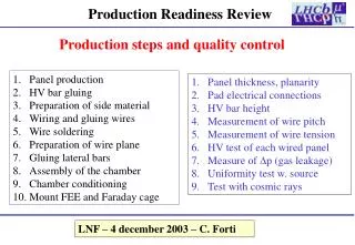
7. TDB production schedule Quality assurance procedure The quality assurance procedure includes the following steps: 1. High temperature treatment. Each board will be kept at 100C during 100 hours. 2. Visual inspection. 3. DC-tests. The potentials will be measured in specified points in order to check the working conditions. 4. Functionality tests. All important characteristics will be measured and compared to acceptance window: - Time constant and amplification factor - Linearity - Crosstalk (few channels from each board) - Noise Boards, which do not pass the tests, will be rejected and repaired if possible. E.Ladygin, L.Kurchaninov
7. TDB production schedule Quality assurance procedure QC setup (exists): • Rectangular pulse generator • Digital oscilloscope • PC and control SW E.Ladygin, L.Kurchaninov