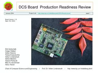
DCS Board Production Readiness Review
350 likes | 549 Vues
DCS Board Production Readiness Review. January 2004 Project Link : http://www.kip.uni-heidelberg.de/ti/DCS-Board/current/ page 1. Board Version 1.16 Sept./ Oct. 2003. Dirk Gottschalk Holger Höbbel

DCS Board Production Readiness Review
E N D
Presentation Transcript
DCS BoardProduction Readiness Review January 2004 Project Link : http://www.kip.uni-heidelberg.de/ti/DCS-Board/current/ page 1 Board Version 1.16Sept./ Oct. 2003 Dirk Gottschalk Holger Höbbel Volker Kiworra Tobias Krawutschke Volker Lindenstruth Stefan Martens Vojtech Petracek Marc R. Stockmeier Heinz Tilsner Chair of Computer Science and Engineering / Prof. Dr. Volker Lindenstruth / http://www.kip.uni-heidelberg.de/ti/
DCS board requirementsOverview Operating Conditions Basic Functional TestsBasic Electrical TestsRadiation Testresults Error HandlingStatusKnown Issues and ChangesSchematics prototype version 1.16 / revised version 1.51Bill of Material version 1.16(plain text)Layout prototype version 1.16 (zipped pdf)Cost ( Not public. See confidential appendix document )Supplier List (plain text. Not public. See confidential appendix document ) DCS Board Production Readiness Review Content Page 2
DCS Board Requirements for ALICE TRD : Clock distribution for MCM modules Control of MCMs via LVDS connections JTAG programming features for reconfiguration JTAG master capability for adjacent neighborhood revitalisation ADCs for voltage and temperature monitoring Magneticless Ethernet for magnetic field applications Control of 24 voltage regulators on Readout Boards Clock recovery from optical link via TTCrx Separat PLL design for FPGA independent clock availability while reboot or reconfiguration Common I/Os for user specific configuration 256MBit min. SDRAM and 32MBit min. Flash EPROM Maximum mechanical height : 16 mm incl. ROB DCS Board Production Readiness Review Page 3
DCS Board Production Readiness Review Page 4 DCS board schematicoverview.
DCS Board Production Readiness Review Page 5 DCS board clock distribution.
DCS Board Production Readiness Review Page 6 DCS board mechanicalhight view on Readout Board.
DCS Board Production Readiness Review Page 7 DCS board connector pinout. D.Gottschalk
DCS Board Production Readiness Review DCS board I/O Configuration Options. Fixed I/Os : Page 8 D.Gottschalk
DCS Board Production Readiness Review DCS board I/O Configuration Options. Fixed I/Os : Page 9 D.Gottschalk
DCS Board Production Readiness Review Page 10 DCS board ethernet concept :Contains Easynet FPGA design as MAC and a magneticlesssolution with an opamp driver for magnetic field applications. Easynet design by Tobias Krawutschke
Operating Conditions :Input Voltage : 3,8 .. 4,2 V ( tested down to 3,3V with Linux still responding.) Temperature : +15 … +25 °CCurrent Consumption : ~ 900mA Power Dissipation : ~ 3,6W at 4Volt DCS Board Production Readiness Review Page 11
Basic Functional Tests :Voltages : okayARM and FPGA : okaystandart JTAG : okayDCS special JTAG : tbdMemory : up to 135MHz okay / 120MHz guaranteedFlash EPROM : okayVreg Shutdown CPLD : tbd ( no problems expected / clock distribution CPLD worked well )ADC : okayLVDS / SCSN : okayEthernet ( with and without transformer ) : 10MBit okay, 100MBit okay but not guaranteedTTCrx : okay ( Configuration with FPGA tested by T. Alt at Bergen/Norway )Optolink : okayOptocouplers : okay DCS Board Production Readiness Review Page 12
Basic Electrical Tests :Voltages : Noise/Ripple below 80mV with Linux booting, idle below 20mV Linux still active down to 3.3 V power supply input. ( 3.0 V behind voltage regulator / measured statically )LVTTL Signals on EPXA1 and CPLDs : okay but have over/undershotEthernet Link : no errors on link with 65m cable length (10MBit) with magneticless ethernet.ADC Noise, Distortion, Stability : tbdLVDS signals : okayDCS board runs up to 45MHz master clock. ( =135MHz memory clock ) DCS Board Production Readiness Review Page 13
DCS Board Production Readiness Review Jitter of FPGA PLL Page 14 The PLL was connectedto a standart output pinon FPGA. For the measurementthe scope triggered onsignal „PLL-FPGA“. V. Kiworra
DCS Board Production Readiness Review Jitter CPLD Page 15 Jitter measurement with one logic gatein CPLDJitter : 840ps V. Kiworra
DCS Board Production Readiness Review Jitter measurement from TTCrx input to PLL output with ICS601 Page 16 green curveICS601-01 PLL output Jitter = 840ps blue curve TTCrx input Jitter = 360ps red curve TTCrx output Jitter = 280ps Triggered on TTCrx output V. Kiworra PLL was fed by 74HCT161 counter.
DCS Board Production Readiness Review Jitter measurement with ICS601 at 3,38 Volt Page 17 V. Kiworra
DCS Board Production Readiness Review Jitter measurement with ICS601at 4,23 Volt Page 18 Phase shows dependency on supply voltage.3,3 volt supplyquality will be enhanced. V. Kiworra
DCS Board Production Readiness Review Radiation Beamtest Page 19 Assumption of total radiation dose for ALICE TPC6 x 109 particles ( n,p,Pi,K ) in 10 ALICE years per 1cm²with 6 x 10⁸ protons 3,5 x 10⁹ pions and kaons 1,9 x 10⁹ neutrons( Source : TPC meeting October 2003 )
DCS Board Production Readiness Review Radiation Beamtest Results (1) : Page 20 *1) D. Gottschalk/KIP, S. Martens/KIP, M. Stockmeier/PI, P. Struck/KIP, H. Tilsner/KIP at University of OSLO November 2003*2) L. Musa / CERN made rad tests as well at CERN and University of OSLO.*3) Links provide documents for details.
DCS Board Production Readiness Review Radiation Beamtest Results (2) : Page 21 *1) D. Gottschalk/KIP, S. Martens/KIP, M. Stockmeier/PI, P. Struck/KIP, H. Tilsner/KIP at University of OSLO November 2003*2) L. Musa / CERN made rad tests at CERN and University of OSLO.*3) Links provide documents for details.
DCS Board Production Readiness Review Radiation Beamtest Plots : 256Mb SDRAM Micron MT48LC16M16 Page 22 16MB used for test Error rate : 1 error per ALICE year per 16MB Test plots by Stephan Martens Diploma Thesis 2003 SDRAM Beam Test Plot
DCS Board Production Readiness Review Radiation Beamtest Plots : Page 23 First error after 146 x 10 ALICE years 1nA Beam current Test plots by Stephan Martens Diploma Thesis 2003 Flash EPROM Beam Test Plot
DCS Board Production Readiness Review Radiation Beamtest Plots : Altera EPXA1 FPGA Page 24 Design :„Coprozessor“ with full FPGA usage. Test plots by Stephan Martens Diploma Thesis 2003 EPXA1 FPGA Beam Test Plot
DCS Board Production Readiness Review Radiation Beamtest Plots : Altera EPXA1 ARM core Page 25 Test plots by Stephan Martens Diploma Thesis 2003 EPXA1 ARM Core Beam Test Plot
DCS Board Production Readiness Review Radiation Beamtest Plots : Voltage regulators MIC29301 Page 26 * => 55 x 10 ALICE years Tests by M. Stockmeier and D. Gottschalk
DCS Board Production Readiness Review Radiation Beamtest Plots : Voltage regulator LP3962 Page 27 * => 107 x10 ALICE years Tests by M. Stockmeier and D. Gottschalk
DCS Board Production Readiness Review Radiation Beamtest Plots : LP3962 recovery over night Page 28 60000 samples => 11 hours Tests by M. Stockmeier and D. Gottschalk
DCS Board Production Readiness Review Radiation Beamtest Plots : ADC AD7708BRU Page 29 * is equivalent to90 x 10 ALICE years Tests by M. Stockmeier and D. Gottschalk
DCS Board Production Readiness Review Radiation Beamtest : Others Page 30 CPLD Test : at 20pA in 2421s one error at 281s at 50 pA in 1079s one error at 49s at 100pA in 741s one error at 288s device dead after 126 x 10 ALICE yearsTested with a twin shiftregister. Looking for nonequal values in both shifters and life activity of design.LVDS Receiver : at 20pA in 2021s no error at 50pA in 2835s no errorLVDS Driver : at 20pA in 1799s no error equivalent to 37,5 x 10 ALICE years Tested with SCSN design in FPGA. Looking for data packet consistency. Tests by M. Stockmeier and D. Gottschalk
DCS Board Production Readiness Review Radiation Beamtest : Others Page 31 Optocoupler : 20pA 30min 2.5ms pulses no effect 50pA after 9min 12.5ms pulses dead 100pA after 15min 12.5ms pulses dead no pulse inversion occuredTested with rectangular pulses looking for erroneous puls inversions or dead.Ethernet Phy : 20pA >40min no errors equivalent to 50 x 10 ALICE years Tested with connection to a PC. Looking for lost or corrupted data packets.Ethernet driver Opamp : 20pA >40 min no errors equivalent to 50 x 10 ALICE years Tested with connection to a PC. Looking for lost or corrupted data packets. Tests by M. Stockmeier and D. Gottschalk
DCS Board Production Readiness Review Radiation Beamtest : Results Page 32 Results where quite encouraging.We found no „No go“.With some devices self-healing was observed.Mean time to failure is : 21 days for one DCS board
DCS Board Production Readiness Review Error Handling : Page 33 Adjacent neighbourhood revitalisation over RS422 JTAG is provided for serious DCS board failure.SCSN rings are redundant.Monitoring of supply voltages and temperature is provided.Voltage regulators can be disabled if unrecoverable short circuits occur.Essential software could be stored multiple in Flash Memoryfor detection of code consistency.Flash can be reprogrammed by adjacent DCS board. Periodic reboots may ensure clean work.
DCS Board Production Readiness Review Page 34 Status :Linux is running sufficiently.Ethernet is running in all configurations ( with transformer and with opamp driver. )Production preparation is in progress. Industry contacts are made.First production batch (50) expected in April/May 2004
Known issues and changes for next revisionQPLL will be replaced because of high cost, unnecessary high jitter performance and high input requirements. DIMM connector will be replaced because of mechanical forces in ROB and DCS board 1V8 Voltage regulator will be fed by 3V3 Regulator minor errors fixed Further radiation test are in progress DCS Board Production Readiness Review Page 35