Download
1 / 40
420 likes | 663 Vues
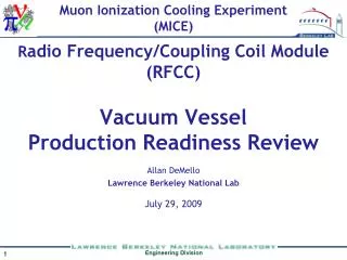
Muon Ionization Cooling Experiment (MICE). R adio Frequency/Coupling Coil Module (RFCC) . Vacuum Vessel Production Readiness Review. July 29, 2009. Allan DeMello Lawrence Berkeley National Lab. MICE Beamline. Radio Frequency/Coupling Coil Module (RFCC). RFCC Quarter Section View.

E N D
Muon Ionization Cooling Experiment (MICE) Radio Frequency/Coupling Coil Module (RFCC) Vacuum Vessel Production Readiness Review July 29, 2009 Allan DeMello Lawrence Berkeley National Lab
Vacuum Vessel Exploded Major Components of the Vacuum Vessel
Overview of Fabrication Procedure • Fabricate of vacuum vessel in 3 sections – two 316L stainless steel flanged sections and one 316L stainless steel central sleeve • Assemble 3 vacuum vessel sections to the coupling coil (in appropriate fixturing) • Verify alignment of all vacuum vessel components • Weld all joints and gussets • Weld on the vacuum pump manifolds and RF feedthroughs • Leak check vacuum vessel
Vacuum Vessel to Coupling Coil Gussets Align gussets to coupling coil and tack weld to vacuum vessel Tack weld a stainless steel bar across the gusset pairs to help maintain their position • Remove vessel section from the coupling coil and complete the welding of the gussets to the vessel
Vacuum Vessel Central Sleeve • Precision machined central sleeve • 5.08mm (0.200 in.) wall thickness • 1384.93mm O.D. • 1374.77mm I.D.
Weld on Manifold and Feedthroughs Vacuum Vessel and Coupling Coil Assembly
Vacuum Vessel Analysis • Calculate stress for thin walled pressure vessel • Analyze vacuum vessel per 2007 ASME Boiler and Pressure Vessel Code VIII, Division 1 • ANSYS analysis for vessel with external pressure • ANSYS analysis for the 50-ton magnetic load • ANSYS analysis for tilting to horizontal position • ANSYS analysis for lifting from four points
ASME Boiler and Pressure Vessel Code Charts used to find Factor A and Factor B which are used in ASME Boiler and Pressure Vessel Code Calculations Outside Diameter ÷ Wall Thickness = Do/t Length ÷ Outside Diameter = L/Do Factor B Factor A Factor A
Minimum Wall Thickness (2007 ASME Boiler and Pressure Vessel Code)
Design Verification – External Pressure (2007 ASME Boiler and Pressure Vessel Code)
Design Verification – Internal Pressure (2007 ASME Boiler and Pressure Vessel Code) • A burst disc will be installed on the vessel to avoid the possibility of over-pressure (25psi max)
Design Verification – External Pressure (1/3 Vessel) (2007 ASME Boiler and Pressure Vessel Code)
Design Verification – External Pressure (2007 ASME Boiler and Pressure Vessel Code)
ANSYS Analysis ANSYS Analysis
Model of Vacuum Vessel for ANSYS • 14.7 psi external pressure applied to stainless steel vessel
ANSYS Results - Equivalent Stress • 14.7 psi external pressure applied to stainless steel vessel • 1888 psi maximum equivalent (von Mises) stress • Maximum allowable stress for 316L stainless steel from ASME Boiler and Pressure Vessel Code is 16,700 psi • Weld efficiency of 60% reduces the maximum allowable stress to 10,020 psi • With the de-rated welds the maximum stress is 5.3 times less than the maximum allowable stress
Model - Vessel With Gussets Added • 14.7 psi external pressure applied to stainless steel vessel
ANSYS Results - Equivalent Stress • 14.7 psi external pressure applied to stainless steel vessel with gussets • 2041 psi maximum stress • Weld efficiency of 60% reduces the maximum allowable stress to 10,020 psi • With the de-rated welds the maximum stress is ~5 times less than the maximum allowable stress
Bellows Bridge Bolts Bellows pulled back for module clearance Bridge bolts – exterior view • Bridge bolts are needed to transmit the potential 50-ton magnetic force when the magnet quenches • 36 - ten millimeter bolts will bridge the RFCC to AFC bellows Bridge bolt – section view
Model – Vessel with Bridge Bolts 36 bolts in flange • Stand fixed at base pads • Vessel fixed at bolt face • 50-ton load applied to coupling coil
50 Ton Magnetic Force -36 Bridge Bolts • A 50 ton force is applied to the coupling coil • The vacuum vessel has an increased density to simulate the presence of the cavities • 36 bridge bolts per side to transfer the load to the rest of the MICE beamline. • von Mises max stress of 32,263 psi on bolt cross section • Strain hardened 316L stainless steel bolts which have a yield strength of 100,000 psi (minimum) will be used to bridge the bellows
Tilting of Vacuum Vessel The vacuum vessel will be tilted from the vertical (operational) position to the horizontal (shipping) position. It will be tilted back again to the operational position in the U.K. RF cavities are removed for shipping
ANSYS Analysis - Tilting of Vacuum Vessel • The vacuum vessel is modeled in ANSYS to simulate hanging from 2 of the pick points. • The cavities are assumed to be removed. • Ends of vacuum vessel are capped with 0.375 thick aluminum • The force of gravity is applied 6867 psi equivalent stress is well below yield stress for 316L stainless steel of 42000 psi
Lifting of RFCC Assembly Anticipating the possibility that the complete RFCC module will be lifted using the 4 pick points provided for tilting the assembly - an ANSYS analysis of the lifted assembly was done
Lifting the RFCC Assembly – ANSYS Results • The vacuum vessel is modeled in ANSYS to simulate hanging from the 4 pick points. • The cavities are assumed to be in place. • Ends of vacuum vessel are capped with 0.375 thick aluminum • The force of gravity is applied 10161 psi equivalent stress is well below yield stress for 316L stainless steel of 42000 psi
Summary • Because of the tight interface between the O.D. of the vacuum vessel and the I.D. of the coupling coil the vacuum vessel is assembled from three major parts • The two flanged section are fabricated in several steps to minimize the distortion of the welding • The central sleeve is precision machined to guarantee it will fit into the coupling coil I.D. • Analysis verifies the ability of the vacuum vessel to withstand the vacuum loads • Strain hardened 316 stainless steel bridge bolts will be needed to transfer the magnetic loads through the bellows joint • Tilting and lifting are possible with this design