Download
1 / 78
870 likes | 1.22k Vues
Principles of Magnetic Resonance Imaging. J. Peter Mustonen (from David J. Michalak) Presentation for Physics 250 05/01/2008. Outline. Motivation Principles of NMR Interactions of spins in B 0 field Principles of 1D-MRI Principles of 2D-MRI Summary. Motivation.

E N D
Principles of Magnetic Resonance Imaging J. Peter Mustonen (from David J. Michalak) Presentation for Physics 250 05/01/2008
Outline • Motivation • Principles of NMR • Interactions of spins in B0 field • Principles of 1D-MRI • Principles of 2D-MRI • Summary
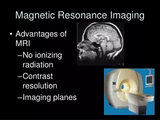
Motivation Magnetic Resonance Imaging provides a non-invasive imaging technique. Pros: -No injection of potentially dangerous elements (radioactive dyes) -Only magnetic fields are used for imaging – no x-rays Cons: -Current geometries are expensive, and large/heavy www.nlm.nih.gov
Principles of NMR B0 Application of prepolarizing magnetic field, B0, aligns the spins in a sample to give a net magnetization, M. M rotates about B0 at a Larmor precession frequency, w0 = gB0 M = SMi
Principles of NMR z RF Pulse B0 B0 M y x Application of prepolarizing magnetic field, B0, aligns the spins in a sample to give a net magnetization, M. M rotates about B0 at a Larmor precession frequency, w0 = gB0 Application of a rf pulse w0=2pf0 along the x-axis will provide a torque that displaces M from the z axis towards y axis. A certain pulse length will put M right on xy plane M = SMi
Principles of NMR z z RF Pulse B0 B0 Time exp[-iw0t] B0 M M y y x x Application of prepolarizing magnetic field, B0, aligns the spins in a sample to give a net magnetization, M. M rotates about B0 at a Larmor precession frequency, w0 = gB0 Application of a rf pulse w0=2pf0 along the x-axis will provide a torque that displaces M from the z axis towards y axis. A certain pulse length will put M right on xy plane M precesses in the transverse plane. In the absence of any disturbances, M continues to rotate indefinitely in xy plane. M = SMi
Principles of NMR z z RF Pulse B0 B0 Time exp[-iw0t] B0 M M y y Detector x x Application of prepolarizing magnetic field, B0, aligns the spins in a sample to give a net magnetization, M. M rotates about B0 at a Larmor precession frequency, w0 = gB0 Application of a rf pulse w0=2pf0 along the x-axis will provide a torque that displaces M from the z axis towards y axis. A certain pulse length will put M right on xy plane M precesses in the transverse plane. In the absence of any disturbances, M continues to rotate indefinitely in xy plane. M = SMi
Principles of NMR z z RF Pulse B0 B0 Time exp[-iw0t] B0 M M y y Detector x x Application of prepolarizing magnetic field, B0, aligns the spins in a sample to give a net magnetization, M. M rotates about B0 at a Larmor precession frequency, w0 = gB0 Application of a rf pulse w0=2pf0 along the x-axis will provide a torque that displaces M from the z axis towards y axis. A certain pulse length will put M right on xy plane M precesses in the transverse plane. In the absence of any disturbances, M continues to rotate indefinitely in xy plane. • Assume: • All spins feel same B0. • No other forces on Mi (including detection). M = SMi
Principles of NMR z z RF Pulse B0 B0 Time exp[-iw0t] B0 M M y y Detector x x (w0/2p)-1 Application of prepolarizing magnetic field, B0, aligns the spins in a sample to give a net magnetization, M. M rotates about B0 at a Larmor precession frequency, w0 = gB0 Application of a rf pulse w0=2pf0 along the x-axis will provide a torque that displaces M from the z axis towards y axis. A certain pulse length will put M right on xy plane signal, sr(t) time, t M = SMi
Principles of NMR z z RF Pulse B0 B0 Time exp[-iw0t] B0 M M y y Detector x x (w0/2p)-1 Application of prepolarizing magnetic field, B0, aligns the spins in a sample to give a net magnetization, M. M rotates about B0 at a Larmor precession frequency, w0 = gB0 Application of a rf pulse w0=2pf0 along the x-axis will provide a torque that displaces M from the z axis towards y axis. A certain pulse length will put M right on xy plane sr(t) t FT sr(w) w w0= 2pf0 M = SMi
Principles of NMR z z RF Pulse B0 B0 Time exp[-iw0t] B0 M M y y Detector x x (w0/2p)-1 Application of prepolarizing magnetic field, B0, aligns the spins in a sample to give a net magnetization, M. M rotates about B0 at a Larmor precession frequency, w0 = gB0 Application of a rf pulse w0=2pf0 along the x-axis will provide a torque that displaces M from the z axis towards y axis. A certain pulse length will put M right on xy plane sr(t) t FT sr(w) w w0= 2pf0 Boring Spectrum! M = SMi
Principles of NMR z B0 y x Complexity Makes Things Interesting • In Reality: • Relaxation (Inherent even if B0 is homogeneous) • T1: Spins move away from xy plane towards z. • T2: Spins dephase from each other. • B0 inhomogeneity. • Chemical Shift.
Principles of NMR z B0 y x T1 Spin Relaxation • T1 Spin Relaxation: return of the magnetization vector back to z-axis. • Spin-Lattice Time Constant: • Energy exchange between spins and surrounding lattice. • Fluctuations of B field (surrounding dipoles ≈ receivers) at w0 are important. Larger E exchange necessary for larger B0→ longerT1. • Math: dM/dt = -(Mz-M0)/T1 • Solution: Mz = M0 + (Mz(0)-M0)exp(-t/T1) • After 90 pulse: Mz = M0 [1-exp(-t/T1)] • M0 = net magnetization based on B0. • Mz = component of M0 along the z-axis. • t = time
Principles of NMR z B0 y x T2 Spin Relaxation • T2 Spin Relaxation: Decay of transverse magnetization, Mxy. • T1 plays a role, since as Mxy→Mz, Mxy→ 0 • But dephasing also decreases Mxy: T2 < T1. • T2: Spin-Spin Time Constant • Variations in Bz with time and position. • Pertinent fluctuations in Bz are those near dc frequencies (independent of B0) so that w0 is changed. • Molecular motion around the spin of interest. • Liquids: High Temp more motion, less DB, high T2 • Solids: slow fluctuations in Bz, extreme T2. • Bio Tissues: spins bound to large molecules vs. those free in solution. Mxy z B0+DB(r,t) y x
Principles of NMR z B0 y x T1/T2 Spin Relaxation Comparison of T1 and T2 Spin Relaxation: *200 for arterial blood, 100 for venous blood. B0 = 1.5 T, 37 degC (Body Temp) Magnetic Resonance Imaging: Physical Principles and Sequence Design, Haacke E.M. et al., Wiley: New York, 1999. z B0+DB(r,t) y • Math: dM/dt = -Mxy/T2 • After 90 pulse: Mxy = M0 exp(-t/T2)] x
Principles of NMR z B0 y x T1/T2 Spin Relaxation Comparison of T1 and T2 Spin Relaxation: *200 for arterial blood, 100 for venous blood. Magnetic Resonance Imaging: Physical Principles and Sequence Design, Haacke E.M. et al., Wiley: New York, 1999. z T2 << T1 Mxy decays ~exp(-t/T2) B0+DB(r,t) Because T2 is independent of B0, higher B0 gives better resolution y 2/T2 FT sr(t) x t w0 Detector FID Spectrum
Principles of NMR z B0 y x T1/T2 Spin Relaxation • Inclusion of T1 and T2 Spin Relaxation: • Inclusion of mathematical expression: • Bloch Equation z g = gyromagnetic ratio T1 = Spin-Lattice (longitudinal-z) relaxation time constant T2 = Spin-Spin (transverse-x/y) relaxation time constant M0 = Equilibrium Magnetization due to B0 field. i, j, k = Unit vectors in x, y, z directions respectively. B0+DB(r,t) y x
Principles of NMR z B0 y x T1/T2 Spin Relaxation • Inclusion of T1 and T2 Spin Relaxation: • Inclusion of mathematical expression: • Bloch Equation Precession Transverse Decay Longitudinal Growth z g = gyromagnetic ratio T1 = Spin-Lattice (longitudinal-z) relaxation time constant T2 = Spin-Spin (transverse-x/y) relaxation time constant M0 = Equilibrium Magnetization due to B0 field. i, j, k = Unit vectors in x, y, z directions respectively. B0+DB(r,t) y x Net magnetization is not necessarily constant: e.g., very short T2, long T1.
Principles of NMR z B0 y x Chemical Shift • Chemical Shift: Nuclei are shielded (slightly) from B0 by the presence of their electron clouds. • Effective field felt by a nuclear spin is B0(1-s). • Larmor precession freq, w = gB0(1-s). • Shift is often in the ppm range. • ~500,000 precessions before Mxy = 0 • Chemical environment determines amount of s. • H2O vs. Fat (fat about 3.5 ppm lower w0) z 2d- B0(1-s) O C y d+ d+ H H H H x Discrete Shift Less Shielding More Shielding Detector
Principles of NMR z B0 y x Chemical Shift Chemical Shift: Nuclei are shielded (slightly) from B0 by the presence of their electron clouds. Ability to resolve nuclei in different chemical environments is key to NMR 2/T2 z w0 w0(1-s) B0(1-s) Because T2 is independent of B0, higher B0 gives better resolution y x Discrete Shift Detector
Principles of NMR z B0 y x Field Inhomogeneity • T2*: B0 Inhomogeneity: Additional decay of Mxy. • In addition to T2, which leads to Mxy decay even in a constant B0, application of dB0(x, y, z, t) will cause increased dephasing: 1/T2* = 1/T2 + 1/T’, where T’ is the dephasing due only to dB0(x, y, z, t). • T2* < T2, and depends on dB0(x, y, z, t). • Additional loss of resolution between peaks. time, t z B0+dB(r,t) y x
Principles of NMR z B0 y x Field Inhomogeneity • T2*: B0 Inhomogeneity: Additional decay of Mxy. • In addition to T2, which leads to Mxy decay even in a constant B0, application of dB0(x, y, z, t) will cause increased dephasing: 1/T2* = 1/T2 + 1/T’, where T’ is the dephasing due only to dB0(x, y, z, t). • T2* < T2, and depends on dB0(x, y, z, t). • Additional loss of resolution between peaks. • If dB0(x, y, z) is not time dependent, then it can be corrected by an echo pulse. time, t z B0+dB(r,t) y x
Principles of NMR z B0 y x Field Inhomogeneity • T2*: B0 Inhomogeneity: Additional decay of Mxy. • In addition to T2, which leads to Mxy decay even in a constant B0, application of dB0(x, y, z, t) will cause increased dephasing: 1/T2* = 1/T2 + 1/T’, where T’ is the dephasing due only to dB0(x, y, z, t). • T2* < T2, and depends on dB0(x, y, z, t). • Additional loss of resolution between peaks. • If dB0(x, y, z) is not time dependent, then it can be corrected by an echo pulse. time, t z z z B0+dB(r,t) B0+dB(r,t) B0+dB(r,t) y y y time, t 180x pulse (x → x, y → –y) x x x Echo!
Principles of NMR z B0 y x Field Inhomogeneity • T2*: B0 Inhomogeneity: Additional decay of Mxy. • If echo pulse applied at time, t, then echo appears at 2t. • Only T’ can be reversed by echo pulsing, T2 cannot be echoed as the field inhomogeneities that lead to T2 are not constant in time or space. • 4) Signal after various echo pulsed displayed below. T2 T2* sr(t) t t’ 180 pulse applied t 180 pulse applied 2(t’-t) Echo 2t Echo t = 0 90 pulse
Principles of 1DMRI Single B0 – No Spatial Information Measured response is from all spins in the sample volume. Detector coil probes all space with equal intensity B0 B0 B0 time 90 pulse Detector coil If only B0 is present (and homogeneous) all spins remain in phase during precession (as drawn). - B(x, y, z, t) = B0; thus, w(x, y, z) = w0 = gB0 2/T2 FT No Spatial Information (Volume integral) sr(t) t w0 FID Spectrum
Principles of 1DMRI Slice Selection: z-Gradient Slice selection along z-axis. Gradient in z and selective excitation allows detection of a single slice. B(z) = B0 + Gzz Gz Field strength indicated by line thickness Gz = dBz/dz integrate Bz=Gzz It follows that: B(z=0)=B0
Principles of 1DMRI Slice Selection: z-Gradient Slice selection along z-axis. Gradient in z and selective excitation allows detection of a single slice. B(z) = B0 + Gzz Gz Selective 90 pulse wrf=w0+gGzz Field strength indicated by line thickness Gz = dBz/dz integrate Bz=Gzz It follows that: B(z=0)=B0
Principles of 1DMRI Slice Selection: z-Gradient Slice selection along z-axis. Gradient in z and selective excitation allows detection of a single slice. B(z) = B0 + Gzz • Larmor Precession frequency is z-dependent: • w(z) = gB(z) • w(z) =g(B0 + Gzz) • w(z) = w0 + gGzz Gz Selective 90 pulse wrf=w0+gGzz Field strength indicated by line thickness • Excite only one plane of z ± Dz by using only one excitation frequency for the 90 pulse. For example, using B0 for excitation: only spins at z=0 get excited. All other spins are off resonance and are not tipped into the transverse plane. Gz = dBz/dz integrate Bz=Gzz It follows that: B(z=0)=B0
Principles of 1DMRI Slice Selection: z-Gradient Slice selection along z-axis. Gradient in z and selective excitation allows detection of a single slice. B(z) = B0 + Gzz Gz Selective 90 pulse wrf=w0+gGzz • In practice, you must bandwidth match the frequency of the 90 pulse with the desired thickness (Dz) of the z-slice. (i.e., with a linear gradient, the Larmor precession of spins within z = 0 ± Dz oscillate with frequency w0 ± gGzDz. Thus, BW = 2gGzDz.) • 4) To apply a “boxcar” of frequencies w ± gGzDz, we need the 90 deg excitation profile to be a sinc function in time. • FT(sinc) = rect Field strength indicated by line thickness Gz = dBz/dz integrate Bz=Gzz It follows that: B(z=0)=B0 FT 90° z ± Dz w t sinc = (sinx)/x
Principles of 1DMRI Slice Selection: z-Gradient Gradient Echo Pulse. Gradient Echo pulse restores all spins to have the same phase within the slice Dz. B(z) = B0 + Gzz Before Gradient Echo t = t z Gz Selective 90 pulse w0+gGzDz w0 w0-gGzDz Spins out of phase on xy plane Pulse Sequence RF Gradient Echo Gz t 3t/2 time 0
Principles of 1DMRI Slice Selection: z-Gradient Gradient Echo Pulse. Gradient Echo pulse restores all spins to have the same phase within the slice Dz. B(z) = B0 + Gzz Before Gradient Echo t = t z Gz Selective 90 pulse w0+gGzDz w0 w0-gGzDz Spins out of phase on xy plane Pulse Sequence Top View of xy plane w0 w0-gGzDz w0+gGzDz RF t=t Gradient Echo Gz t 3t/2 time 0
Principles of 1DMRI Slice Selection: z-Gradient Gradient Echo Pulse. Gradient Echo pulse restores all spins to have the same phase within the slice Dz. B(z) = B0 + Gzz Before Gradient Echo t = t z Gz Selective 90 pulse w0+gGzDz w0 w0-gGzDz Spins out of phase on xy plane Pulse Sequence Top View of xy plane w0 w0-gGzDz w0+gGzDz RF After Gradient Echo t = 3t/2 t=t Gradient Echo z Gz t=3t/2 t 3t/2 time 0 Spins all IN phase
Principles of 1DMRI Slice Selection: z-Gradient Slice selection along z-axis. Gradient in z and selective excitation allows detection of a single slice. B(z) = B0 + Gzz Gz Selective 90 pulse
Principles of 1DMRI Slice Selection: z-Gradient Slice selection along z-axis. Gradient in z and selective excitation allows detection of a single slice. B(z) = B0 + Gzz Gz Selective 90 pulse time Detector coil
Principles of 1DMRI Slice Selection: z-Gradient Slice selection along z-axis. Gradient in z and selective excitation allows detection of a single slice. B(z) = B0 + Gzz Gz Selective 90 pulse time Detector coil exp(-t/T2) No x, y Information, but only spins from the z ± Dz slice contribute to the signal. 2/T2 FT sr(t) t w0 FID Spectrum If we can encode along x and y dimensions, we can iterate for each z slice.
Principles of 1DMRI Frequency Encoding Perform z-slice. Now only look at 2D plane from now on. Use Gradient along x to generate different Larmor frequencies vs. x-position. y y z z z Selective 90 pulse in z ± Dz time x x x 2Dz Bz(x) - B0 Apply x-Gradient Gx = dBz/dx Precession Frequency varies with x
Principles of 1DMRI Frequency Encoding Perform z-slice. Now only look at 2D plane from now on. Use Gradient along x to generate different Larmor frequencies vs. x-position. y y z z z Selective 90 pulse in z ± Dz time x x x 2Dz Bz(x) - B0 w(x) w0 w0 + gGxx w0 - gGxx Frequency Encoding along x Apply x-Gradient Gx = dBz/dx Precession Frequency varies with x
Principles of 1DMRI Frequency Encoding Perform z-slice. Now only look at 2D plane from now on. Use Gradient along x to generate different Larmor frequencies vs. x-position. z Pulse Sequence RF x Gz Bz(x) - B0 Detector coil Gx w(x) time 0 w0 w0 + gGxx w0 - gGxx Detect Signal “readout” Gx on while detecting
Principles of 1DMRI Frequency Encoding Perform z-slice. Now only look at 2D plane from now on. Use Gradient along x to generate different Larmor frequencies vs. x-position. z T2* is based on the intentionally applied gradient. exp(-t/T2*) sr(t) t x FT FID Bz(x) - B0 Detector coil w(x) w0 w0 + gGxx w0 - gGxx 2/T2* Apply x-Gradient DURING acquisition. Precession Frequency varies with x. w0 - gGxx w0 w0 + gGxx
Principles of 1DMRI Frequency Encoding Perform z-slice. Now only look at 2D plane from now on. Use Gradient along x to generate different Larmor frequencies vs. x-position. z T2* is based on the intentionally applied gradient. exp(-t/T2*) sr(t) t x FT FID Bz(x) - B0 Detector coil w(x) w0 w0 + gGxx w0 - gGxx 2/T2* Apply x-Gradient DURING acquisition. Precession Frequency varies with x. Spins at various x positions in space are encoded to a different precession frequency w0 - gGxx w0 w0 + gGxx
Principles of 1DMRI Imaging Example Two Microfluidic Channels. Water only exists in two microfluic channels as shown. y y Application of Gx z z z 90 pulse time x x x Dz Bz(x)
Principles of 1DMRI Imaging Example Two Microfluidic Channels. Water only exists in two microfluic channels as shown. y y Application of Gx z z z 90 pulse time x x x Dz Bz(x) • No spins exist at x=0 where Gx=0 (w0): FT of signal has no intensity at w0. • Signal is the line integral along y. (Still no info about y distribution of spins.) Image m(x,y) = spin density(x,y) w0 - gGxx w0 w0 + gGxx
Principles of 1DMRI 1DFT Math Signal is the 1DFT of the line integral along y. Homodyne the signal (from w0 to 0).
Principles of 1DMRI 1DFT Math Signal is the 1DFT of the line integral along y. Homodyne the signal (from w0 to 0). Let g(x) = Line integral along y for a given x position.
Principles of 1DMRI 1DFT Math Signal is the 1DFT of the line integral along y. Homodyne the signal (from w0 to 0). Let g(x) = Line integral along y for a given x position. Spatial frequency Gxt ~ kx The homodyned signal is thus the Fourier Transform (along x) of the line integral along y.
Principles of 1DMRI k-vector perspective Time Evolution of Spins in an x-Gradient. Spatial frequency, k-vector, changes. SMi(x) w0 w0 + gGxx w0 - gGxx x t1 Pulse Sequence RF time Gz Dephasing across x in time. Rotating frame w0 or relative to x=0 Gx time 0 t1 t2
Principles of 1DMRI k-vector perspective Time Evolution of Spins in an x-Gradient. Spatial frequency, k-vector, changes. SMi(x) w0 w0 + gGxx w0 - gGxx x t1 Pulse Sequence RF time Gz Dephasing across x in time. Rotating frame w0 or relative to x=0 Gx time 0 t1 t2
Principles of 1DMRI k-vector perspective Time Evolution of Spins in an x-Gradient. Spatial frequency, k-vector, changes. SMi(x) w0 w0 + gGxx w0 - gGxx x t1 Pulse Sequence RF time Gz Dephasing across x in time. Rotating frame w0 or relative to x=0 Gx time 0 t1 t2
Principles of 1DMRI k-vector perspective Time Evolution of Spins in an x-Gradient. Spatial frequency, k-vector, changes. SMi(x) w0 w0 + gGxx w0 - gGxx x t1 Pulse Sequence RF time Gz Dephasing across x in time. Rotating frame w0 or relative to x=0 Gx time 0 t1 t2
Principles of 1DMRI k-vector perspective Time Evolution of Spins in an x-Gradient. Spatial frequency, k-vector, changes. SMi(x) w0 w0 + gGxx w0 - gGxx x t1 Pulse Sequence RF time Gz Dephasing across x in time. Rotating frame w0 or relative to x=0 Gx time 0 t1 t2