Download

1 / 13
130 likes | 389 Vues
Semi-Active Rocking Wall Systems for Enhanced Seismic Energy Dissipation. K.J. Mulligan, M. Fougere, J.B. Mander, J.G. Chase , G. Danton, R.B Elliott Departments of Mechanical and Civil Engineering, University of Canterbury, Christchurch B.L Deam

E N D
Semi-Active Rocking Wall Systems for Enhanced Seismic Energy Dissipation K.J. Mulligan, M. Fougere, J.B. Mander, J.G. Chase, G. Danton, R.B Elliott Departments of Mechanical and Civil Engineering, University of Canterbury, Christchurch B.L Deam Leicester Steven EQC Lecturer in Earthquake Engineering, University of Canterbury, Christchurch Sponsor: EQC Research Grant # 03/497
Why Semi-active? • Broad range of control • respond to changes in structural behaviour/response • Resistive forces when most beneficial due to added information from sensor(s) • significant added damping can be added to systems • guaranteed stability • Supplemental damping for all rocking cycles, not only subsequently larger cycles as with tendon or some other passive designs • Relatively very simple to implement from design equations suitable for use in standard design methods (see talk #2 Thursday 10:30-12:00, Session Th10 Rm 226) • Customised control of hysteresis loops (see same talk) It’s all about providing effective, practicable, repeatable structural response energy management
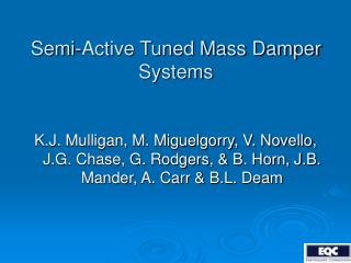
Wr Fd Roof Wr R h b O’ O O Fd Simple Rocking Wall Device Better device locations are possible (?)
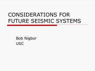
Valve and valve controller Test Jig Valve Resetable Device Test Machine Piston Cylinder Device Two chambered design: • Utilises each side independently • Resetting can occur at any piston displacement • Portions of motion may have both valves open • Existing experimentally validated models (linear and nonlinear) 20-100kN devices using air as the working fluid!
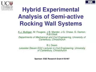
Cc Slope depends on stiffness of semi-active device Slope = -1 Semi-Active Rocking Wall Non-linear device Wall starts to rock • Resist motion away • Allow gravity and free fall to dissipate max energy (a 1-3 device) • A = area of extra dissipated energy Pre-tensioned Tendon “Flag” Schematic (see Mander et al) Only 1 “flag” per tendon unless the rocking angle increases
Method & Analysis • Design with free vibration = initial tradeoff analysis: • Peak reduction factors, R.F and equivalent viscous damping, ξ • Several initial angles • Normalise results to uncontrolled case for design over several device stiffness values • Approximately 6, 11, 16% effective added stiffness compared to uncontrolled period of motion (1, 5, 10 kN/m devices) • Analyse results with forced vibration: • Same performance metrics (R.F. and ξ) • Suite of ground motions used to analyse efficacy of semi-active system to a realisticvariety possible events • Medium suite from SAC project as it has mix of near and far field events of “good size” • ‘Maximum events’ with 475 yr return period
Free Vibration • Device only restricts motion away • Hence, initial slopes to 0deg are the same • Non-linear impact on wall period • Stiffer devices lead to faster attenuation • However, less cycles is less attenuation! Less stiff devices lead to longer period due to lesser effect on reducing amplitude Device begins to act only on first cycle away from equilibrium
Free Vibration Summary • 5kN/m or more (>10% of effective stiffness) shows significant effect • RFs are non-linear over stiffness • Added effective damping is significant (6-14%), minimum of 5% • All values rise as initial angle rises showing that longer stroke provides increasing effect – as expected for a stiffness based damping device
Typical Seismic Response • Initial rocking unchanged in this case • Number of cycles is reduced • Less enhancement of rocking as at 10sec of K=0 case • Very stiff device has almost no rocking and thus almost no energy dissipation from the rocking system (good?) K = 0 K = 1kN/m K = 5kN/m K = 10kN/m
Seismic Response • Similar results, however differences between devices are smaller • Area inside hysteresis curve (A) adds another dissipation metric based on number of cycles and device stiffness • Variation is very high across the suite due to significant changes in period and thus amplitude as device stiffness rises, as well as variation in records • Note that a less stiff devices oscillate more and thus may dissipate more energy A significant design tradeoff
Summary • Semi-Active rocking systems offer the opportunity for significant added energy dissipation in a repeatable fashion using these devices • Particularly applicable to joints with low inherent structural damping • Thus, suitable for damage avoidance designs • Semi-Active rocking systems designed and analyzed, and the tradeoffs presented in terms of standard structural design metrics of R.F. and added viscous damping x • Effects of devices are non-linear with device size (and likely placement) • Performance metrics are characterised statistically over suites of ground motions to account for realistic variation and a broad range of possible inputs • Outcomes are suitable for performance based design methods or developing design equations similar to a spectral analysis approach. • Approach can be generalised to any similar design or system or device, such as joints with low inherent structural damping
The Future? • Full-scale experimental validation • Other designs • Tendons and multiple devices at sides of wall to provide greater forces in resistance • Sacrificial tendons? • Better models and analysis of larger building systems incorporating semi-active rocking dissipation to more fully understand the benefit that might be gained and for what structures.
Acknowledgements Special thanks to Ms Kerry Mulligan, Mr. Maxime Fougere and all our co-authors This research was funded by the NZ Earthquake Commission (EQC) Research Foundation and an ENISE, St. Etienne Research Travel Grant