Coincidence Module for PET
Coincidence Module for PET. Wu, Jinyuan FNAL Mar. 2009, LBNL. From Talk by Bill Mosses. Numbers. Assumption: 8 inputs/board 4 hits/input/(160 ns) Therefore the data processing throughput of the FPGA in the coincident board is: 32 hits/(160 ns) 200 M hits/s. Not too bad.

Coincidence Module for PET
E N D
Presentation Transcript
Coincidence Module for PET Wu, Jinyuan FNAL Mar. 2009, LBNL
From Talk by Bill Mosses Wu, Jinyuan, Fermilab, jywu168@fnal.gov
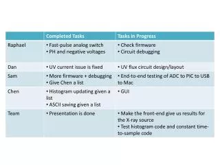
Numbers • Assumption: • 8 inputs/board • 4 hits/input/(160 ns) • Therefore the data processing throughput of the FPGA in the coincident board is: • 32 hits/(160 ns) • 200 M hits/s. • Not too bad. 4 hits/(160 ns) Buffer & Merge 200 M hits/s Dual Port RAM Wu, Jinyuan, Fermilab, jywu168@fnal.gov
Assumption on Hit Information Coarse Time 6b, LSB=2.5ns Fine Time 7b, LSB=2500/128ps Channel Number and Crystal ID: 12-18b The reorganized data will still have O(n^2) combinations. Up to 1024-32=992 comparisons are needed for 32 hits. Time Slot 5b, LSB=5ns 32 hits/(160 ns) (max) The hit time has a random order. 200 M hits/s Wu, Jinyuan, Fermilab, jywu168@fnal.gov
The First Pass: Hash Sorting Coarse Time 6b, LSB=2.5ns Time Slot 5b, LSB=5ns The hash sorter coincident engine can find coincident in two passes of the data. This is the first pass, using n (=32) clock cycles. • When the data words are clocked in at 200 MHz, the time slot is used as the write address of a memory block. The data word is written into the addressed memory location. • Each memory location represents a 5ns interval of the hit time. • After the first pass, the hit data are stored in the memory indexed by hit time. (Many memory locations are empty.) Wu, Jinyuan, Fermilab, jywu168@fnal.gov
The Second Pass: Outputting Coincident • The data are clocked through again and the time slot is used as read address. • If a non-empty location is readout and the stored hit has a different channel number as the current hit, the two hits are in the same time slot. This is a potential good coincident. • If three hits falls into the same 5ns time slot, there should be three coincident possibilities, this algorithm can find two. (What shall we do with this?) Ch Ch != This is the second pass, using another n (=32) clock cycles. Not Equal Good Coincident Wu, Jinyuan, Fermilab, jywu168@fnal.gov
Boundary Coverage. • In addition to the location addressed by the time slot, another adjacent location is also readout. The choice of which adjacent location is determined by the LSB of the coarse time (2.5ns). • Coincident condition with two possibilities are checked. • The two readout can be implemented by reading out in two clock cycles. != Ch Ch != Good Coincident Wu, Jinyuan, Fermilab, jywu168@fnal.gov
Single FPGA for Coincident of a Camera • The input data from 8 inputs are merged into a 200 MHz data stream. • Four Hash Sorter Coincident Engines process 1/4 of total time slices, each with two passes + memory clean up etc. Hash Sorter Coincident Engine 4 hits/(160 ns) Buffer & Merge Hash Sorter Coincident Engine 200 M hits/s Hash Sorter Coincident Engine Hash Sorter Coincident Engine Wu, Jinyuan, Fermilab, jywu168@fnal.gov
Hash Sorter • Silicon area saving comes from two factors: • Higher clock speed: 25 MHz -> 200 MHz, x8. • Hash Sorter Algorithm (or indexing algorithm): O(n^2) -> O(n), x32. • The Hash Sorter in this document is a simplified version that supports one hit per bin. A full feature version can be found: • http://www-ppd.fnal.gov/EEDOffice-w/Projects/ckm/comadc/PID26561.pdf • http://www-ppd.fnal.gov/EEDOffice-w/Projects/ckm/comadc/lowpt_lecc2004p.pdf Wu, Jinyuan, Fermilab, jywu168@fnal.gov
A Better Design See the next slides
Different detector sectors (45 degrees each in this example) can be stored in different bins addressed by the sector number. Each sector corresponds to an input in the coincident card. Multiple hits in the same time bin but different sectors will not be overwritten. Coincidence of hits in a sector are searched in the opposite 2 sectors. Ensuring a coverage up to 45 degrees in the opposite side for any hit. The search in the 2 opposite sectors are denoted as DS=3.5 and DS=4.5. For example, for hits (or seeds) in the channels in the lower half of the sector 0, the DS=3.5 search will address sector 3 and the DS=4.5 search will address sector 4. See table. In time domain, coincidence is searched in 2 time bins, ensuring +-2.5ns coverage. Similarly the are denoted as DT=-2.5ns and DT=+2.5ns. For each seeding hit, a total of 4 bins are to be readout from the hash sorter. Partitioning in Both Time and Space 1 2 3 0 7 4 6 5 5ns 5ns 5ns Wu, Jinyuan, Fermilab, jywu168@fnal.gov
Hash Sorter Booking Process Coarse Time 6b, LSB=2.5ns Sector: 2b Write Address = (Time Slot (5ns) 5b, Sector 2b) Hits in sector 3,4,5,6 are booked into the hash sorter, preparing for coincidence search seeded by hits in sectors 0,1. Wu, Jinyuan, Fermilab, jywu168@fnal.gov
Hash Sorter Search Process • The hash sorter is readout 4 times for any seed hit, i.e., DS=3.5 and 4.5 with DT=+-2.5ns. The addresses are generated using adders. • The no-same-channel coincident condition is automatically satisfied. • Other coincident conditions can be applied. DS=3.5, DT=-2.5ns DS=4.5, DT=+2.5ns DS=3.5, DT=-2.5ns DS=4.5, DT=+2.5ns Hits in sectors 0,1 are used as seeds to search possible coincidence with hits in sectors 3,4,5,6 stored in the hash sorter. Coincident Logic Good Coincident Wu, Jinyuan, Fermilab, jywu168@fnal.gov
If two hits A & B meet coincident condition, they will be found twice, i.e., (A,B) and (B,A) when A and B are used as “seeds”, respectively. To eliminate duplicated pairs, only hits on the sectors 0-3 of the detector are used as seed. This way, most pairs will only be found once. When the seed is in sector 3, coincidences only with hits in sector 7 are valid, not sector 0. Coincidences between sectors 0 and 3 are already searched when the seed are in sector 0. See the table. Avoiding Duplicated Coincident Pairs 1 2 3 0 7 4 6 5 Wu, Jinyuan, Fermilab, jywu168@fnal.gov
The hash sorter engine is implemented with two dual port RAMs, with a write port and a read port each. The RAMs are arranged in 4 pages and each page stores data from one time slice (160n each). Continuous time coverage is provided this way allowing coincidences across time slice boundary being found. The entire process above takes 32 clock cycles, 16 for booking, 16 for erasing and 8 for each checking. Booking, erasing the hash sorter are performed at the write port while the coincidence checking is at the read port. The writing and reading are done simultaneously but are in different time slice pages. The coincidence checking is primarily in TS=N-1 page. However, during DT=-2.5ns checking, bins at the boundary in the TS=N-2 page may be addressed. The DT=-2.5ns checking processes are arranged in the first 16 clock cycles in which TS=N-2 page is not erased. Similarly, during the DT=+2.5ns checking, bins at the boundary in the TS=N page may be addressed. The DT=+2.5ns processes are arranged in the later 16 clock cycles in which TS=N page is already booked. Dual Port RAM Write Port Read Port Dual Port RAM Write Port Read Port BOOK TS=N BOOK TS=N CHECK TS=N-1 CHECK TS=N-1 ERASE TS=N-2 ERASE TS=N-2 Some Implementation Details BOOK Time Slice TS=N Sectors 3,4,5,6 ERASE Time Slice TS=N-2 Sectors 3,4,5,6 CHECK TS=N-1 Seed Sectors 0,1 DT=-2.5ns, DS=3.5 CHECK TS=N-1 Seed Sectors 0,1 DT=-2.5ns, DS=4.5 CHECK TS=N-1 Seed Sectors 0,1 DT=+2.5ns, DS=3.5 CHECK TS=N-1 Seed Sectors 0,1 DT=+2.5ns, DS=4.5 BOOK Time Slice TS=N Sectors 4,5,7,0 ERASE Time Slice TS=N-2 Sectors 4,5,7,0 CHECK TS=N-1 Seed Sectors 2,3 DT=-2.5ns, DS=3.5 CHECK TS=N-1 Seed Sectors 2,3 DT=-2.5ns, DS=4.5 CHECK TS=N-1 Seed Sectors 2,3 DT=+2.5ns, DS=3.5 CHECK TS=N-1 Seed Sectors 2,3 DT=+2.5ns, DS=4.5 Wu, Jinyuan, Fermilab, jywu168@fnal.gov
The input data from 8 sectors (corresponding to 8 inputs) are merged into 200 MHz data streams. Two data streams are used to book/erase the hash sorter and two streams are used to seed the coincidence search. A single hash sorter coincident engine with two dual port RAMs provides full coverage of continues time. Dual Port RAM Write Port Read Port Dual Port RAM Write Port Read Port BOOK TS=N BOOK TS=N CHECK TS=N-1 CHECK TS=N-1 ERASE TS=N-2 ERASE TS=N-2 Single FPGA for Coincidence of a Camera Hash Sorter Coincidence Engine 200 MHz 4 hits/(160 ns)/Sector Booking Sectors 3,4,5,6 Buffer & Merge Seeding Sectors 0,1 Booking Sectors 5,6,7,0 Seeding Sectors 2,3 Wu, Jinyuan, Fermilab, jywu168@fnal.gov
Another Approach The Semi-Classical Trigger Approach
Three Approaches • Parallel Coincidence FPGAs: • Need many FPGAs or a large FPGA to fight the combinatorial problem. • Hash Sorter: • Can be implemented in one small FPGA. • A limit such as 4 hits/(160 ns)/sector must be applied, since full data (32 bits) are sent for each raw hit. • Semi-classical Trigger Approach: • Coincidence base on just hit time, 1bit/5ns. Wu, Jinyuan, Fermilab, jywu168@fnal.gov
Assume the all the Detector Processing Boards are synchronized with a global clock and a serial data link “Hit” at 200Mbits/s (maybe LVDS in a pair of Cat-5 cable with RJ-45 connector, 250Mbits/s with 8B10B coding) is sent out from the Detector Processing Board. (In Parallel Coincidence FPGA scheme or Hash Sorter scheme, at least 800Mbits/s is needed.) Each bit represents a 5ns interval and each 8-bit (16-bit) word represents a 40ns (80ns) time frame. Hits from different detector modules are combined together using bit-wise OR function. With the “Hit” link, the time of the hits can be transmitted at precision of 5ns. DetectorProcessingBoard Hit Time Coding and Transmitting CLK&CMD 0 1 0 0 0 0 0 0 0 0 0 0 0 0 0 0 Hit 0 0 0 0 0 1 0 0 0 0 0 0 0 1 0 0 0 1 0 0 0 1 0 0 5ns 40ns Wu, Jinyuan, Fermilab, jywu168@fnal.gov
In normal trigger system, the cable carrying hit pulse must have well controlled delay. With serial data link, it is not necessary: the cable can have any delay/latency and temperature dependency. At system initialization, all the Detector Processing Boards send out a special word in the same clock cycle as start mark. At the receiving end, the absolute arrival time from each board can be unknown and different. However, the start mark is recognized and stored in the addresses 0 of the corresponding receiving buffer. The words after the start mark are stored in sequence. The hit streams are realigned in the receiving buffer. Cable Delay Self Timing Detector Processing Board Detector Processing Board Detector Processing Board Processing Support Board Wu, Jinyuan, Fermilab, jywu168@fnal.gov
Hits from different inputs in the Processing Support Board are merged together with an OR function and sent out as a serial data stream. The Coincidence Module re-align the different stream in the receiver buffers. Inside the Coincidence Module, the coincidence is searched as AND functions of the hit streams from opposite detector sectors. Very likely, a boundary coverage logic is applied, e.g.: Trigger T[N] = HA[N]&&(HB[N] || HC[N]). The boundary coverage for time domain is also necessary. This is satisfied by checking adjacent bits in the buffered words, e.g.: Trigger T[N] = (HA[N+1] || HA[N] || HA[N-1])&&(HB[N] || HC[N]). Hit Merging and Coincidence Processing Support Board Coincidence Module Processing Support Board Wu, Jinyuan, Fermilab, jywu168@fnal.gov
The CLK & Command signal provide time reference to the Detector Processing Boards and also carries small amount of data as fast commands. It should be able to pin point a specific clock cycle in which the command is to be executed. Trigger is a fast command. The trigger command requires the Detector Processing Boards to send out the data from the pipeline memory in the 2-3 clock cycles in which the coincidence occurred. One choice of the CLK & Command signal format is the Clock-Command Combined Carrier Coding (C5) in a pair of Cat-5 cable with RJ-45 connector. DetectorProcessingBoard Clock and Command Signal CLK&CMD Hit Wu, Jinyuan, Fermilab, jywu168@fnal.gov
The Clock-Command Combined Carrier Coding (C5) • A data train contains 5 pulses and each pulse is transmitted in four unit time intervals, usually in four internal clock cycles at frequency f. • Information is carried with wide, normal and narrow pulses and the first pulse is always wide or narrow. • When not transmitting data, all pulses have normal width. • The data stream is DC balanced over 5 pulses suitable for AC coupled transmission. • All leading edges are evenly spread so that the pulse train can be used directly drive the receiver side logic or PLL. Wu, Jinyuan, Fermilab, jywu168@fnal.gov
After power up, the clock is established using the input of CLK&CMD signal as time reference. A reset command is sent to the Detector Processing Board to reset local counters. At the reset, the Hit data link sends out a start marker and then continuously send the data words with each bit representing a hit in a 5ns time interval. The Hit streams are merged in the Processing Support Board and coincidence is checked in the Coincidence Module. If there is a coincidence, a trigger command is encoded into the CLK&CMD signal. The trigger command causes full hit data output from a serial link “Data”. This can be the third LVDS pair in the same Cat-5 cable with a RJ-45 connector. The fourth pair can be assigned as commands for slow control. Operating & Interconnection Summary 1 CLK&CMD Detector Processing Board 3 Hit 2 A Cat-5 Cable w/ RJ-45 Connector Data 4 Slow Control Commands? Wu, Jinyuan, Fermilab, jywu168@fnal.gov
The End Back Up Slides
If two hits A & B exist within +-2.5ns and opposite +-1 sectors from each other, they will be found twice, i.e., (A,B) and (B,A) when A and B are used as “seed”, respectively. To eliminate duplicated pairs, only hits on the sections 0-7 of the detector are used as seed. This way, most pairs will only be found once. When the seed is in section 7, coincidences only with hits in sections E & F are valid, not section 0. Coincidences between section 0 and 7 are already searched when the seed are in section 0. Storage in Hash Sorter for sections 0-6 is not necessary. But they still exist. Avoiding Duplicated Coincident Pairs 3 4 2 5 1 6 7 0 F 8 E 9 A D B C Wu, Jinyuan, Fermilab, jywu168@fnal.gov