Mobile and Pervasive Computing - 5 Future Communication Technologies
530 likes | 581 Vues
Explore Li-Fi technology - data transmission through LED light bulbs. Learn about advantages, challenges, and applications in various sectors.

Mobile and Pervasive Computing - 5 Future Communication Technologies
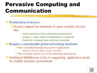
E N D
Presentation Transcript
Mobile and Pervasive Computing - 5Future Communication Technologies Presented by: Dr. Adeel Akram University of Engineering and Technology, Taxila, Pakistan http://web.uettaxila.edu.pk/CMS/AUT2015/teMPCms
Outline • Light Fidelity (Li-Fi) • Radio over Fiber in the Home Area Network
Contributed by Mr. ShujaShabbir 1000112206 CSE-4
WHAT IS LI – FI ? Li-Fi stands for ‘Light Fidelity’ LI-FI is transmission of data through illumination, sending data through a LED light bulb that varies in intensity faster than human eye can follow
INTRODUCTION OF LI-FI It is a VLC (Visible Light Communication), technology developed by team of scientists including Dr. Gorden Povey, Prof. Harald Hass and Dr. Mostafa Afgani at University of Edinburgh, UK Li-Fi is now part of Visible Light Communication (VLC) PAN IEEE 802.15.7 Standard. ”Li-Fi is typically implemented using white LED light bulbs” These device are normally used for illumination by applying a constant current through the LED Li-Fi is the term used to label the fast and cheap wireless communication system, which is the optical version of Wi-Fi Li-Fi is light based Wi-Fi that is, it uses light instead of radio waves to transmit information
IMPORTANT ABOUT LI-FI Instead of Wi-Fi modems, Li-Fi would use transceivers-fitted LED lamps that can light a room as well as transmit and receive information This technology uses a part of the electromagnetic spectrum that is still not greatly utilized – i.e. The Visible Spectrum. Li-Fi, as it has been dubbed, has already achieved high speeds in the lab. Researchers at the Heinrich Hertz Institute in Berlin, Germany, have reached data rates over 500 Megabytes per second using a standard white-light LED.
CAPACITY Radio waves Cost and Expensive Less Bandwidth compared to other spectrums Insufficient spectrum for increasing data
EFFICIENCY Millions of base stations consume huge amount of energy for 1.Transmitting the radio waves 2.To cool the Base Station cabins 5% Efficiency
AVAILABILITY • Available within the range of Base Stations • Limited availability • Unavailable in aircrafts SECURITY: • Less secure (passes through the walls)
INFRARED RAYS IN REMOTE CONTROL • Single data stream • 20000 bits per second • Not usable for video streaming
WORKING OF LI- FI • The brilliant idea was first showcased by Prof. Harald Hass in his TED Global Talk on VLC. • http://www.ted.com/talks/harald_haas_wireless_data_from_every_light_bulb.html • He explained,”very simple, if the LED is on, you transmit a 1 and when LED off transmit a 0.The LED can be switched on and off very quickly, which gives nice opportunities for transmitting data.” • Further enhancements can be made in this method, like using an array of LEDs for parallel data transmission, or using mixtures of red, green and blue LEDs to alter the light’s frequency encoding a different data channel.
TRANSMITTING ELEMENT • LED • Fluorescent Lamp
RECEIVING ELEMENT (DETECTOR) • Avalanche Photo Diode • Image Sensors
ADVANTAGES AND DISADVANTAGES ADVANTAGES • Larger bandwidth (10,000 times the radio bandwidth) • High efficiency • More availability • Highly secure
DISADVANTAGES • Presence of Light is essential • There will be interference from sunlight • You need special LEDs
Li-Fi How Does It Work? Who is making it? What is the catch? Fudan University in Shanghai are finding a way to wirelessly transfer information using light instead of radio waves. Li-fi can only work if the light illuminating from the Li-fi LED can be picked up by the receiving device. Li-fi works with regular, plain old LED lights which are found everywhere. Data is sent to the LEDs, and they flicker rapidly in a pattern. A camera made for sensing light can then pick up the frequency and read the pattern like morse code. Won’t the constant flickering of the lights become annoying? Sunlight can interfere with your Li-fi connection even through windows. You would have to use Li-fi in a room with no windows, and you would not be able to turn out the lights. Dimmed lights may result in lost data, and slower connections. The LEDs are flickering so quickly, that it would appear as a steady stream of light. Normal florescent office lights flicker 20,000 times per second. Li-fi flickers billions of times per second. That’s a lot of data! Because light runs on a much higher frequency than radio waves, data transferred with radio waves is limited. Researchers began working with light outside the visible spectrum to combat these disadvantages. Li-fi can transfer data at a rate of 1Gbit/s They claim that using infrared lights could work outside and even boost connection speeds to 5 gigs per second. Different colors of LEDs could transfer data on different signals.
CONCLUSION http://www.ted.com/talks/harald_haas_wireless_data_from_every_light_bulb.html Li-Fi Overcomes the limitations of radio spectrum High speed of 10 Gbps can be achieved Li-Fi can solve the for essential problems of wireless communications these days
RADIO OVER FIBER FOR AN OPTIMAL 60 GHZ HOME AREA NETWORK Authors / Contacts:
Contents • Radio over Fiber in the Home Area Network • An example of optical architecture: multipoint-to-multipoint • Setup and results • Using the radio MAC layer for driving the optical infrastructure
Radio over Fiber in the Home Area Network • As the number of connected devices in the home increases, the rates necessary between each of them increases too. • The ultimate goal in home network, and for a provider of tele-communications like Orange, is to satisfy the demand made by this new services like remote backup, video conference, video on demand, voice over IP, data exchange in high-definition …
Radio over Fiber in the Home Area Network • We need high rates in the whole home because the devices and our home gateway are not necessary in the same room. Workspace Computer and NAS Children’s Parent’s bedroom bedroom HomeGateway Garage Laptop and Phone Living-room Kitchen Television and Games console
Radio over Fiber in the Home Area Network • The wireless connectivity is generally preferred for the final link to the device (easy to use and very flexible). • In the future, IEEE 802.11.ad will be the radio standard to transport data at very high throughputs (above 1Gbps), • But, this radio standard has a short range (less than 10m). How can we enlarge the coverage of the radio signal ?
Remote antenna : converts electrical signal (radio) to optical signal, and vice-versa Two optical fibers (downlink and uplink). We transport radio signals in their native format (analogue) on an optical carrier Radio over Fiber in the Home Area Network Workspace Garage Kitchen Living-room Children’s Parent’s bedroom bedroom
Radio over Fiber in the Home Area Network So, the Radio over Fiber system enlarges the coverage of the radio signal itself. It consists in transporting the radio signal from wireless devices onto an optical carrier for distribution over optical fibre to different remote antennas. The optical link acts as an analogue repeater. Transporting the radio signals in their native format, provides the advantage of remote antenna simplification and transparency to radio layer protocols. Optical In Photodiode Direct modulation issimple and low cost. TX A DC antenna DC Block The remote antenna has small size, light weight and low power consumption. Bias Tee RX TEE A antenna Laser RF Filter Optical Out Automatic Gain Control
Radio over Fiber in the Home Area Network • Why optical fibers ? • Only the fiber optic can enlarge the coverage of radio signal transparently. • It offers a very high bandwidth and low attenuation, thus can transfer the high rate of the radio over several hundred meters. • It will be a natural extension of access networks (Fiber To The Home). • It is the ideal candidate to provide long life-span local networks.
Radio over Fiber in the Home Area Network • Besides, the Radio over Fiber optimizes the global spectral efficiency. • Indeed, power is radiated only in the spot (room) where it is useful. • We have a full control of the range of radio wave (no trouble of the radio signals of neighbours, health and hacking concerns).
Contents • Radio over Fiber in the Home Area Network • An example of optical architecture: multipoint-to-multipoint • Setup and results • Using the MAC layer for driving the optical infrastructure
Workspace Garage Gateway + ONT Kitchen Living-room NxN Splitter An example of optical architecture:multipoint-to-multipoint Two optical fibers Power is radiated only in the spot where it is useful (Space) and when it is necessary (Moment). Children’s Parent’s bedroom bedroom Fiber To The Home
RoF 1 RoF 1 RoF 1 RoF 2 RoF 2 RoF 2 RoF 3 RoF 3 RoF 3 RoF 4 RoF 4 RoF 4 An example of optical architecture:multipoint-to-multipoint Remote antenna without intelligence RoF 1 RoF 2 Is equivalent to RoF 3 RoF 4 Gateway + ONT NxN Splitter Wireless device with radio chipset
An example of optical architecture:multipoint-to-multipoint • Main advantages / disadvantages : • Self-sufficient system: the distribution of resources managed by the radio MAC layer. • No intelligence required: direct communication possible. • Optical budget should allow the NxN optical splitter (16x16 = 12dB). • Two optical fibers required per remote antenna.
Contents • The Radio over Fiber in the Home Area Network • An example of optical architecture: multipoint-to-multipoint • Setup and results • Using the radio MAC layer for driving the optical infrastructure
Setup and results Workspace Garage Gateway + ONT Living-room Kitchen Splitter Parent’s Children’s bedroom bedroom Optical splitter ( 8x8 = 9dB ) It behaves as an optical tunnel
Contents • The Radio over Fiber in the Home Area Network • An example of optical architecture: multipoint-to-multipoint • Setup and results • Using the radio MAC layer for driving the optical infrastructure
Using the radio MAC layer for driving the optical infrastructure • The lasers that are turned-on without seeing radio data at the input, are noise for the photodiodes that receive an optical signal from another laser (copy of the ambient noise by adding the noise of the conversions). • Interferences : beat between independent light sources. Noise Workspace Laser ON Signal MAC monitoring Signal Parent’s Children’s Noise bedroom bedroom Garage Gateway + ONT Kitchen Living-room Splitter Noise
Using the radio MAC layer for driving the optical infrastructure • Bridge : MAC Monitoring signal. • Only one of the device (e.g. the gateway) demodulates the radio signal, • Recovers useful data in the radio MAC layer to manage the optical access (turning-on laser or photodiode), • Sends instruction to remote antenna by a monitoring signal.
Conclusion • The example shows the feasibility of a wireless network inside the home with Radio over Fiber for extending the radio coverage. • Then, the Radio over Fiber optimizes the global spectral efficiency. • The optical architectures show good results, and needs information from radio MAC Layer to be managed.
References [1] Ultra Broad Band Wireless Home Network based on 60GHz WPANs cells interconnected via RoF M.Huchard, M.Weiss, A.Pizzinat, S.Meyer, P.Guignard, B.Charbonnier Invited paper IEEE Journal of Lightwave Technology [2] Ultra Wide Band over fibre transparent architecture for high bit-rate home networks A.Pizzinat, F.Payoux, B.Charbonnier, S.Meyer Springer Annals of telecommunication Journal (Special Issue on Home Networking) [3] RNRT/BILBAO project: first results on Ultra Wide Band over fiber S.Paquelet, S.Mallegol, G.Froc, A.Bisiaux, A.Pizzinat, B.Charbonnier, N.Malhouroux, S.Meyer, F.Payoux, I.Siaud, G.Salingue, D.Morche, H.Jacquinot, S.Bories, C.Algani, AL.Billabert, S.Mazer, JL.Polleux, C.Rumelhard, M.Terré, C.Sillans, Y.Le Guennec, B.Cabon, M.Lourdiane, G.Maury International UWB Workshop 2007, Grenoble, France. [4] Ultra Wide Band Home Networks by Means of a Low Cost Radio-over-MultiMode-Fibre Transparent System A.Pizzinat, I.Louriki, B.Charbonnier, S.Meyer, C.Sillans, H.Jaquinot, S.Bories, M.Terré, C.Algani, AL.Billabert, Y.Le Guennec, P.Lombard, G.Froc Network and Optical Communications 2008, Krems (Austria), 1-3 July 2008 [5] Optical fiber infrastructures for UWB access and FTTH B.Cabon, Y.Le Guennec, P.Lombard, M.Lourdiane, JM.Duchamp, A.Pizzinat, I.Louriki, B.Charbonnier, F.Payoux, S.Meyer, M.Terré, C.Algani, AL.Billabert, C.Sillans, H.Jaquinot, S.bories, G.Froc ISIS workshop, Stokholm, June 2008 [6] Low Cost Transparent Radio-over-Fibre System for UWB Based Home Network A.Pizzinat, I.Louriki, B.Charbonnier, F.Payoux, S.Meyer, M.Terré, C.Algani, AL.Billabert, C.Sillans, H.Jaquinot, S.Bories, Y.Le Guennec, G.Froc European Conference on Optical Communications 2008, Bruxelles 21-25 Sept. 2008