Test & Measurement instruments
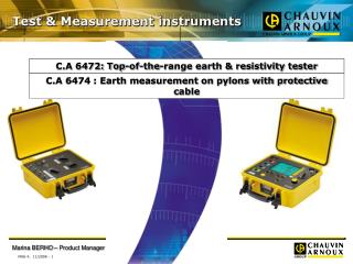
Test & Measurement instruments. C.A 6472: Top-of-the-range earth & resistivity tester. C.A 6474 : Earth measurement on pylons with protective cable. The market: segmentation Positioning in the Chauvin Arnoux range Positioning in relation to the competition

Test & Measurement instruments
E N D
Presentation Transcript
Test & Measurement instruments C.A 6472: Top-of-the-range earth & resistivity tester C.A 6474 : Earth measurement on pylons with protective cable
The market: segmentation • Positioning in the Chauvin Arnoux range • Positioning in relation to the competition • Functional presentation & measurement principle
The earth testers market • Traditional methods for measuring earth impedance : the 3-pole method and the 4-pole method derived from it. • Advantages : accurate results but following disadvantages: • Necessity of disconnecting the earth, • Necessity of setting up auxiliary rods, • Necessity of sufficient room to set up the rods. => often time-consuming and cumbersome. • Other methods available which allow quicker and easier earth measurements =>selective earth measurement( only applicable to parallel earthing systems) • These methods are: • The earth clamp • Measurement with 2 clamps • 3-pole/4-pole measurement + clamp
The earth testers market On the basis of these measurement methods, it is possible to segment the earth testers market as follows: • 1. Entry-level earth testers (such as the C.A 6423 / C.A 6460 / C.A 6462) • 3P / 4P measurement method - Operating frequency 128 Hz • 2. Mid-range earth testers (such as the C.A 6470) • 3P / 4P measurement method - Adjustable measurement frequency to avoid interference voltages • Measurement expert functions • Functions for comfortable measurement: • memorization / rechargeable battery / automatic calculation for resistivity • 3. Top-of-the-range earth testers (such as the C.A 6472) • Measurement method: traditional methods with rods + selective methods • Wide measurement frequency band (up to 5 kHz) to avoid interference voltages and to study the frequency behaviour of an earthing system • Measurement expert functions: same as C.A 6470 • Functions for comfortable measurement: same as C.A 6470
C.A 6410-12-15-15R (Earth clamps) C.A 6462 C.A 6460 (Earth / Resistivity) C.A 6456 (Loop / 1P,2P,3P earth) Positioning in the Chauvin-Arnoux range PRICE C.A 6472 / 74 (Earth / Resistivity / Earth of pylons) C.A 6470 (Earth / Resistivity) € 760 C.A 6423 (3P earth / digital) C.A 6421 (3P earth / analogue) PERFORMANCE Existing products New products
C.A 6472 / C.A 6474: top-of-the range product Earth measurement from 40 Hz to 5 kHz Multi-function earth and resistivity tester for our expert customers • Measurements possible even in the event of highly resistive soils • Improved measurement quality due to high rejection of interference voltages (up to 60 V) • Excellent accuracy and measurement resolution (up to 0.001 resolution for 4P earth measurement)
C.A 6472 / C.A 6474: top-of-the range product Earth measurement from 40 Hz to 5 kHz New features compared with the other products of the Chauvin-Arnoux range • Possibility of performing all types of earth measurements with a single instrument • Addition of selective earth measurement functions => possibility of measurement without disconnecting the earthing system • Analysis of behaviour as a function of the frequency due to a wide measurement frequency band (41 Hz to 5 kHz) • Earth measurements on pylons with protective earth cable (with C.A 6474 option)
C.A 6472 / C.A 6474: top-of-the range product Earth measurement from 40 Hz to 5 kHz • Advantages of selective measurement (only suitable for parallel earthing systems) • Earth loop measurement with 2 clamps: principle equivalent to the earth clamp => Considerable time-saving as it is not necessary to set up the auxiliary rods and disconnect the earth connection • 4P + clamp measurement: accurate selective measurement without disconnecting the earth to be tested => No hazards for property and/or people • Advantages of high-frequency measurements: An earthing system may have an acceptable impedance value at low frequencies, but its behaviour at high frequencies may prove poor due to the inductive effect. => Earth measurement with a frequency scan can be used to study the behaviour of an earthing system according to the frequency, thus allowing its behaviour in the event of a fault (e.g. lightning) to be predicted.
Utility of the expert functions • Measuring the resistances of the auxiliary rods and the interference voltages : • accurate interpretation of the measurements • help users to understand and rectify malfunctions. 1. Measurement of the auxiliary rod resistances • A high rod resistance value influences the measurement accuracy. • Measuring theresistances of the auxiliary rods => find out which one has anexcessively high • value. • Possible to remedy this by adding rods in parallel or by wetting the ground. • 2. Measurement of interference voltages • Presence of interference voltages => alteration of earth and resistivity measurements. • Measuring these voltages enable to find out the extent of their influence on the • measurement result. • The C.A 6470 & C.A 6472 use a symbol to warn users in the event of significant interference • voltages andinclude a system for automatically choosing the test frequency with the least • noise.
TARGET CUSTOMERS • C.A 6472 • Major administrations and public services: SNCF, EDF / RTE and European equivalents, France TELECOM • Inspection organizations • Major electrical installers • Construction and Civil Engineering implementation industries • Maintenance departments in major industries • Geologists • + C.A 6474 • Power transmission companies • Insurance companies • Telecommunications installers (GSM masts)
CA 6472: main functionalities • Continuity & 2P/4P resistance measurement, • Earth: 3P, 4P, 4P+clamp, 2 clamps • Resistivity • Potential measurement • Pylon earth measurement (with C.A 6474) Connection to C.A 6474 Intuitive use due to the colour-coded connection terminals also shown on the screen Direct access to functions Test activation
C.A 6472: main functionalities Navigation on the instrument: A 6-key keyboard for: - CONFIG-FREQUENCY/ DISTANCE: Choice of the measurement configuration (2 or 4 wires for continuity measurement, for example) and measurement frequency / input of distances for resistivity calculation - DISPLAY / SMOOTH: new display and access to the supplementary measurement results / activation or deactivation of smoothing on the measurement result display - MEM / MR: storage of the measurement results in the memory / rereading of stored data - / : in general, incrementation / decrementation of the flashing parameter (example: distance to be entered for the ground resistivity calculation)
APPEARANCE • Rugged, leakproof on-site casing • Compact • Particularly ergonomic • large backlit LCD screen • rotary switch for direct access to measurements • 6-key keyboard • marked E-ES-S-H input terminals • Battery rechargeable on mains or vehicle cigarette lighter
Example: The connection terminals are shown on the display; one is not connected although the measurement selected requires it , so it is flashing APPEARANCE • Large LCD screen - backlit - 3 simultaneous digital display levels for more information - wide range of symbols and indicators
Easy to use • Colour-coded terminals for simpler connections • Reduction in handling errors due to automatic detection of incorrect connections: E, ES, S and H flash on the display if the connection is incorrect • 3 operating modes: • Automatic mode in each function; by default, the instrument performs a measurement at 128Hz and chooses the most appropriate frequency in the event of interference voltages. • A single key is all you need for easy handling: • - selection of a function • - press on the START button • reading of the result • Scan mode (automatic measurements at different frequencies) allowing a graph of impedance as a function of frequency to be plotted • Manual mode (choice of the measurement frequency, display of all the voltages measured, etc.) for expert customers
CONTINUITY MEASUREMENT ( position) • Advantages of this type of measurement: Verification of: • the condition of the measurement cables • the connections between the measurement cables and the measurement rods • the interlinks in a parallel earth network • Characteristics: - methods : 2 wires or 4 wires (compensation of leads possible with 2-wire method) - possibility of reversing the measurement current and calculating the average - resistance range: 0.001 to 100 k - measurement current: 200 mA for R < 20
EARTH MEASUREMENT WITH 3P METHOD ( position) • The 3P method is the traditional rod method for accurately measuring the resistance of an existing earth connection. • Characteristics: • resistance range RE : 0.01 W to 100 kW • adjustable measurement voltage: 16 or 32 Vrms • adjustable measurement frequency: 41 to 5,078 Hz • RS and RH : measurement from 0.1 W to 100 kW • max. Uinterference 60 Vpeak • Selection of the frequency: • This can be done manually (if the user knows a frequency where the interference voltages will be minimal) or in automatic mode (the instrument makes the selection).
EARTH COUPLING MEASUREMENT ( position) • Characteristics: the same as the previous measurements • Advantages of the measurement: - To estimate the reciprocal influence of 2 earth resistances which are not connected to one another, the coupling coefficient must be calculated. - This coefficient should be as low as possible. - In concrete terms, the aim is to prevent a possible fault current flowing in the 1st earth from raising the potential of the 2nd earth. • This type of measurement involves carrying out successive measurements: • Two earth resistance measurements with the 3P method ("3 poles" position) • One 2P resistance measurement ("2 poles" position) After these 3 measurements, the instrument automatically calculates the coupling resistance Rc.
RESISTIVITY MEASUREMENT ( position) • Advantages of the measurement: Assessment of the terrain • to choose the best position for construction of the earth or earth network • to optimize the construction costs and save time when seeking the required earth resistance. • Characteristics: - resistance range RS-SE : 0.01 to 100 k - adjustable measurement voltage: 16 or 32 Vrms - adjustable measurement frequency: 41 to 128 Hz - rod resistances RE, RES, RS and RH: measurement from 0.01 ohms to 100 k - Maximum Uinterference 60Vpeak • The C.A 6472 automatically calculates the resistivity r (Wenner or Schlumberger method) as soon as the distances used for the measurement have been programmed.
RESISTIVITY MEASUREMENT ( position) • The Wenner & Schlumberger methods • Wenner • the distances between the 4 rods are identical: d • rW = 2.p.d.RS-ES • Schlumberger • the distance between the 2 outer rods is 2d • - the distance between the 2 inner rods is A • rS = (p.(d²-A²/4).RS-ES) / 4
GROUND POTENTIAL MEASUREMENT • Lightning: 2 dangers • Risk of direct strike on an individual or installation • Risk of electrification when it strikes close to a person due to the step voltage caused by the lightning. • Principle: • The current source created at the point of impact causes an electrical field • => Voltage on the ground which varies according to the distance from the source • => a difference in potential, or step voltage, occurs between two different points in contact with the ground, increasing with the size of the step.
GROUND POTENTIAL MEASUREMENT Advantages: • Determination of the ground potential value according to the distance • This measurement can be used to obtain a theoretical step voltage value and to determine the region where the potential rise will be the lowest in the event of faults. Measurement principle: Technical characteristics: • Resistance range R S-SE: 0.01 to 100 k • Voltage measurement range: 0.01 mV to 32 V • Voltage generated in open circuit: 16 or 32 Vrms • Adjustable measurement frequency: 41 Hz to 5,078 Hz • Measurement of RS and RH: 0.1 to 100 k maximum • Maximum Uinterference: 60 Vpeak
4P EARTH MEASUREMENT • Based on the same principle as the 3P method • Provides 10 times greater measurement accuracy on the C.A 6472 • Method particularly suitable for measuring very low earth resistances • Very useful for power transmission companies & distributors of electricity
SELECTIVE 4P EARTH MEASUREMENT • Applicable in the case of several resistances set up in parallel • Principle: Measurement of the current flowing in the considered earth thanks to a clamp-on ammeter • This "selective 4P" measurement method provides: • Considerable time savings because it is no longer necessary to disconnect the earth resistance to be measured. Indeed, with the clamp, it is possible to measure the current flowing in the earth connection to be tested, thus removing the influence of the parallel earth connections. • Guaranteed safety for the goods and people in contact with the electrical installation because the earth is not disconnected.
4P AND SELECTIVE 4P EARTH MEASUREMENT • Technical characteristics: • Resistance range R E: 0.001 to 100 k • Voltage generated in open circuit: 16 or 32 Vrms • Adjustable measurement frequency: 41 Hz to 5,078 Hz • Measurement of RS and RH: 0.1 to 100 k maximum • Maximum Uinterference: 60 Vpeak
EARTH LOOP MEASUREMENT WITH 2 CLAMPS • Measurement principle Placing 2 clamps around the earth conductortested and connecting each of them to the Instrument =>1 clamp injects a knownsignal ( 32 V / 1,367 Hz) while the other clampmeasures the current flowing in the loop. This method is based on the same principle as the earth clamp. • Advantages This method saves considerable time during earth testing because it is no longer necessary to: - set up auxiliary rods • - disconnect the earth connections, which is often time-consuming.
EARTH LOOP MEASUREMENT WITH 2 CLAMPS • Technical characteristics: • Resistance range R E: 0.20 to 500 • Resolution: 0.01 to 1 • Accuracy: +/- (5% + 1pt) - Adjustable measurement frequency: 1,367 Hz, 1,611 Hz, 1,758 Hz • Measurement set-up Caution: This method is only applicable if there is a path of low impedance parallel to the connection tested. It is therefore recommended to evaluate the equivalent resistance of the n connections in parallel and ensure that the value is genuinely negligible compared with R E. R = R E + ( RE1 // RE2 // RE3 // ... // REn ) Negligible compared with R E
Advantages of measurements at high frequencies By increasing the frequency of the measurement current, the inductances can be "saturated" and the resistance to be measured can be isolated. Example 1: earth measurement with TN system Equivalent diagram 3P method with a classic 128 Hz frequency The parallel set-up of the resistances is measured. Indeed, a large proportion of the current injected flows in the other loops via the PEN wire.
Example 2:Check that the resistance value measured really is the value of the earth under consideration rather than the result of the parallel set-up of several earths. Indeed, 3P or 4P earth measurement requires disconnection of the earth bar. In some cases, the earthing system is complex and users are not necessarily aware of all the earth connections which they want to measure. Advantages of measurements at high frequencies • High-frequency 3P method • Z PEN becomes infinitely large and this prevents the current from flowing • The entire current injected flows to the earth Re • The value of Re is measured rather than the parallel set-up of the resistances. Resistance In scan mode, if it is observed that the resistance varies according to the frequency => the object measured is not purely resistive => the earth measured is in fact connected to another. frequency
COMPETITION • The C.A 6472 is the only instrument on the market which cansimultaneously: • Carry out earth measurements using all the measurement methods • Carry out high-frequency earth measurements • Carry out earth measurements on pylons with a protective earth cable(with C.A 6474 option) To define its positioning in relation to the market, it must therefore be compared with various types of products: - "multi-method" earth testers - variable-frequency earth testers - high-frequency earth testers
C.A 6474 option: Earth measurement on pylons with protective earth cable Pylons are linked together by a cable called the "protective earth cable" to drain any currents to earth; a high-voltage line is therefore equivalent to a parallel earthing system. Earth cable Equivalent diagram L L L L High-voltage lines Rpylon • Problem: Measuring the earth of a pylon without including the earthing of the other pylons in parallel. The traditional (3P-type) methods require disconnection of the protective earth cable, which is dangerous and time-consuming.
C.A 6474 option: Earth measurement on pylons • Solution: C.A 6474 Carry out selective earth measurement on the pylons without disconnecting the protective earth cable • Equivalent measurement to a selective measurement with clamps, but replacing the clamps with Ampflexes • Use of flexible sensors = any shape of earthing system can be "clamped", unlike with current clamps which are limited by their clamping diameter. • Measurement concept with Ampflexes can therefore be applied to all types of pylon geometries or to earthing systems which are not "traditionally-shaped"; This measurement principle can thus be extended to other types of pylons (GSM masts, etc)
Measurement context Equivalent diagram of a high-voltage line: A traditional 4P measurement cannot yield consistent results when measuring the earth of a pylon. Indeed, much of the current injected flows via the protective earth cable (because it is not very resistive) so the measurement does not give the earth impedance value of the pylon earth under consideration, but the value for the whole of the line. There are two solutions for measuring only the earth resistance of a specific pylon: -either directly measuring the value of the current flowing via the pylon earth to be measured, i.e. carrying out a selective measurement -or reducing the current diverted via the protective earth cable to a negligible value L L L L Current injection point Earth cable Rpylonl Pylon measured EQUIVALENT A Rpylonl Zequivalent Zequivalent Pylon measured
PYLON EARTH MEASUREMENT • The C.A 6474 combines both principles, so it can be used for accurate selective earth measurements on pylons: • The use of Ampflexes => precise measurementof the current flowing in the pylon • A high-frequency measurement => a Zeq value much higher than the earth resistance value to be measured • the current diverted via the protective earth cable to the other pylons becomes negligible and the value of the current flowing via the earth rises • better accuracy of the measurement. • 2 methods of measurement with C.A 6474: • Active method, i.e. with injection of a measurement current by the C.A 6472 • Passive method using the residual currents flowing in the high-voltage line 2 advantages for the passive method: - enable to check the consistency of the measurements obtained with the active method - ensures that measurement results can be obtained whatever the conditions; indeed, highly resistive ground may prevent a sufficient measurement current from flowing, so that the active method cannot be used.
Why choose a maximum frequency of 5 kHz? • Utilitiy of high-frequency earth measurement : • to measure the earth resistance of pylons equipped with a protective earth cable • to forecast the behaviour of an earthing system in the event of lightning. • Frequency of lightning may be up to 1 MHz, but most of the energy is located between 5 and 30 kHz • => Why the C.A 6472 + C.A 6474 is limited to a 5 kHz measurement frequency? • The C.A 6474 measurement concept was developed in close liaison with RTE, the pylon earth measurement specialists in France. • This 5 kHz frequency has been approved by RTE as the frequency providing the best trade-offs between: • the error on the measurement instruments' accuracy • the gain on the ratio of injected current/current in the pylon: indeed, the aim is obtain a sufficient earth current value for accurate earth measurement. • capacitive leakage due to the high frequency • Measurements up to 5 kHz allow extrapolation of the values up to 30 kHz • => Prediction of the earthing system's behaviour in the event of lightning.
PYLON EARTH MEASUREMENT • As well as pylon earth measurements, the C.A 6474 can be used to carry out the following measurements: • Measurement of the impedance of the entire line according to the frequency • the line's behaviour in the event of lightning can be predicted; Indeed, in the event of lightning, the line's impedance must be sufficiently low to allow the fault currents to flow via the protective earth cable and be diverted to earth via the pylons. • Quality of protective earth cable connection: • as the fault currents are diverted via the protective earth cable and then via the pylons, the connection between the two elements must be good.
PYLON EARTH MEASUREMENT Example of measurement: Let us consider a network of 10 pylons in which each pylon has an earth resistance of 10 Test no. 1: 4P method with a "traditional" measurement frequency of 128 Hz Result: R = 2 Test no.2: 4P method with a frequency scan from 41 Hz to 5,078 Hz Test no.3: Selective measurement with the C.A 6474 with frequency scan Test no. 4: Measurement of the impédance of the line with frequency scan
PYLON EARTH MEASUREMENT • Interpretation: • traditional 4P measurement does not allow the genuine earth resistance of the pylon under consideration to be measured • => a 4P earth measurement at 128 Hz gives an earth resistance of 2 instead of 10 . • 2. The traditional 4P method with a frequency scan can be used to gain a rough idea of the real earth resistance value: it is a way of checking the pertinence of the results obtained with the AmpFlex method. • 3. Selective measurement with the C.A 6474: the measurement does not depend on the measurement frequency; it therefore really is the earth value of the pylon considered (purely resistive) which is measured. • 4. Measurement of the line impedance and assessment of protective earth cable connection quality: in the case studied here, the curve representing the line impedance value according to the frequency has no point of inflexion. This means that the impedance will be infinitely large in the event of a fault and will not therefore convey the fault currents in the event of lightning => this line is therefore dangerous.
PYLON EARTH MEASUREMENT • When used with a vectorial processing unit (C.A 6474), the C.A 6472 can be used to measure the earth of pylons with protective earth cables. • Using 4 Ampflex current sensors positioned around the pylon footings and a frequency scan up to 5 kHz, the earth impedance of the pylon considered can be measured precisely and selectively. Technical specifications: • Resistance range RE : 0.01 to 100 k • Voltage generated in open circuit: 16 or 32 Vrms • Adjustable measurement frequency: 41 Hz to 5,078 Hz • RS and RH measurement: 0.1 to 100 k maximum • Maximum Uintereference: 60 Vpeak
MAKING A MEASUREMENT To validate the principle of measurement, we made many field measurements with RTE, specialist in earth measurement of pylons. • 1. Place auxiliary electrodes H and S on opposite sides of the pylon,asfar away as possible and, if possible, perpendicular to thehigh-voltage line • This will eliminate interference with the measurement by spurious voltages or currents induced under the highvoltageline. • 2. In order to avoid electromagnetic interference: • unwind the full length of each cable from the reel • keep the cablesas far apart as possible on the ground • take care not to form loops • avoid placing the cables near or parallel to metallicconductors (cables, rails, fences, etc.).
MAKING A MEASUREMENT • Connections: • Connect the electrodes to terminals H and S. • Connect ES and E a conducting metallic part of the pylonlocatedabove the AmpFLEX sensors. • Connect the required number of AmpFLEX sensors to channels1, 2, 3, and/or 4 (the channels for which they are calibrated)andplace the AmpFLEX loop(s) around the legs of the pylon. • Connect the C.A 6472 and the C.A 6474 together • Attention: • All oftheAmpFLEXloops mustbe oriented in the same directionandthey mustall have the same number of turns. • Do not move or touch the AmpFLEX sensors duringthe measurement, becausethat might cause errors.
MEASUREMENT WITH AMPFLEX According to the position of the AmpFlex in relation to the current injection cable on the pylon, the measurements carried out are different: 1. AmpFlex below current injection: In this configuration, the AmpFlex measures the current flowing to earth I 2 The current measured can therefore be used to obtain the earth resistance value of the pylon considered. Rs I 1 Injection point I 2 I injected =I 1 + I 2 I measured = I 2 • In this configuration, the AmpFlex measures the difference between the current injected and the current flowing to earth • The current measured is the current flowing via the top of the pylon and the protective earth cable • This measurement can therefore be used to measure the line impedance. 2. AmpFLex above current injection Injection point Rs I 1 I 2 I injected =I 1 + I 2 I measured = I injected - I 2 =I 1
Earth measurement whatever the configuration Possibility of measurement without disconnecting the earth bar Wide measurement frequency band: 40 Hz – 5 kHz High rejection of interference voltages Measurement of U h-e, U s-e and Ies interference voltages / currents for better interpretation Possibility of earth measurement whatever the configuration Earth measurement on pylons with protective earth cable: - All types of pylons due to the use of flexible sensors - Accurate, pertinent measurements due to the possibility of measuring at high frequencies Simple, intuitive use Summary: Product advantages of the CA6472/6474
SALES TOOLS SALES LITTERATURE APPLICATION NOTES POSTER
State of delivery • C.A 6472 earth and resistivity tester ............................…………………………….……..P01.1265.04 • Delivered with: • Battery charger • Operating manual in 5 languages on CD-ROM, • Simplified operating instructions • Data export software • Optical / USB communication cable • 2 x C182 clamps • Accessories • C.A 6474 adapter for pylon earth measurement (PYLON BOX) ...............................P01.1265.10 • MN82 clamp for C.A 6472 .......................................................................................P01.1204.52 • Adapter for battery charging on vehicle cigarette lighter ...................................... P01.1020.36 • Optical / RS communication cable...........................................................................P01.2952.52 • Earth & resistivity kit (100 m / 150 m)
State of delivery: C.A 6474 • C.A 6474 adapter for pylon earth measurement (PYLON BOX) .................................P01.1265.10 • Delivered with a carrying bag for accessories containing: • 1 C.A 6472 – C.A 6474 connection cable, • 6 BNC / BNC cables 15 m long for linking the AmpFlexes to the CA6474 • 4 flexible current sensors (AmpFLEX) 5 m long, • 1 set of 12 identification rings for AmpFLEX flexible sensors • 2 cables (5 m green, 5 m black) with safety plugs on winder (cables linking the pylon to the C.A 6472) • 5 spade lug/banana plug adapters, Ø 4 mm, • 3 adjustable clamps: fastening of the cables on the pylon • 1 calibration loop, • Descriptive label AmpFlex BNC cable Adjustable clamp C.A 6472 / C.A 6474 connection cable C182 clamp MN82 clamp
State of delivery: C.A 6474 • C.A 6474 adapter for pylon earth measurement (PYLON BOX) ...........................P01.1265.10 • Delivered with a carrying bag for accessories containing: • 1 C.A 6472 – C.A 6474 connection cable, • 6 BNC / BNC cables 15 m long for linking the AmpFlexes to the C.A 6474 • 4 flexible current sensors (AmpFLEX) 5 m long, • 1 set of 12 identification rings for AmpFLEX flexible sensors • 2 cables (5 m green, 5 m black) with safety plugs on winder (cables linking the pylon to the C.A 6472) • 5 spade lug/banana plug adapters, Ø 4 mm, • 3 adjustable clamps: fastening of the cables on the pylon • 1 calibration loop, • Descriptive label Adjustable clamps AmpFlex