Lecture 12
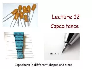
Lecture 12. Capacitance. Capacitors in different shapes and sizes. + Q. - Q. … separated by an insulator (dielectric). Can be air or vacuum . Capacitors. A capacitor is a device whose purpose is to store electric energy which can be released in a controlled manner.

Lecture 12
E N D
Presentation Transcript
Lecture 12 Capacitance Capacitors in different shapes and sizes
+Q -Q … separated by an insulator (dielectric).Can be air or vacuum. Capacitors A capacitor is a device whose purpose is to store electric energy which can be released in a controlled manner. Usually made of two conductorswith charges +Q and –Q…
Usually written as Capacitance: ΔV =V+ – V– Potential difference between the conductors V– V+ Symbol: +Q -Q Capacitance Units: Farad 1 F = 1 C/V
Can be considered infinite planes Example: Parallel plate capacitor Determine the capacitance of two parallel conducting large plates of area A separated by a small distance d. A d
0 0 Between the plates Let the plates have charges +Q and –Q. -Q Q
Capacitance of a parallel plate capacitor: Potential difference between the plates: The charge cancels out…
The capacitance of a system: • Does not depend on: • charge Q, • potential differenceΔV. (because ΔV is always proportional to Q) • Depends on: • the geometryof the system, • the dielectric between the conductors
a b EXAMPLE: Spherical capacitor A capacitor is made of two concentric spherical metal shells of radii a and b. Find the capacitance of the system.
Gaussian surface: sphere of radius r (a < r < b ) a r b We need the potential difference between the spheres when they have charges Q and –Q. → we need the electric field in the region between the spheres. –Q +Q
Potential difference between the two spheres: Capacitance:
Example: Capacitance of a metal sphere of radius a DEMO: Maximum charge of a Van der Graaff Capacitance of a sphere One of the conductors in the capacitor can be (formally) at infinity (capacitor made of one conductor).
C2 C1 C3 A Ceq B A B Combination of capacitors Equivalent (or effective) capacitor Ceq (= “put all the capacitors inside a black box”) No measurement between A and B can distinguish the two circuits above.
A ● C2 C1 B ● Capacitors in series Two capacitors C1 and C2 are in series when they are connected one after the other:
Let a charge +Q1 enter through A and go to the top plate of C1. A charge -Q1 is induced on the bottom plate of C1. +Q1 This was initially an uncharged conductor -Q1 C2 C1 +Q2 -Q2 So +Q2 – Q1 = 0 or Q2 = Q1 Both capacitors are initially uncharged. A ● B ●
+Q2 +Q1 +Qe -Q2 Qe -Q1 And the equivalent capacitor? A ● C1 The charge introduced in the system must be the same: Q1 = Q2 = Qeq C2 B ● A ● +Qeq Ceq -Qeq B ●
A ● V1 = VA – VC C1 C ● V2 = VC – VB C2 Veq = VA – VB B ● A ● Ceq B ● Potential differences: Veq = V1 + V2
… C1 C2 C3 Use series connection to decrease capacitance Note that Capacitors in series: And remember that:
We have two conductors: top and bottom. Capacitors in parallel Two capacitors C1 and C2 are in parallel when the two plates of C1 are connected to the two plates of C2. A ● C2 C1 B ●
A ● Ceq B ● All points on the red conductor have potential VA. All points on the blue conductor have potential VB. A ● C2 C1 B ● = Veq (VA – VB) = V1 = V2
+Qe +Q2 +Q1 Qe -Q2 -Q1 Charges: A ● C1 C2 The charge introduced in the system must be the same: Q1 + Q2 = Qeq B ● A ● +Qeq Ceq -Qeq B ●
C2 C3 Use parallel connection to increase capacitance Note that Capacitors in parallel: … C1 … And remember that:
C1 C2 C3 C1 = 1.0 μF C2 = 2.0 μF C3 = 3.0 μF V0 = 12 V Example: Capacitor circuit For the circuit below, find: • The charge in C1 • The potential difference in C2
C1 C2 C3 C1 = 1.0 μF C2 = 2.0 μF C3 = 3.0 μF V0 = 12 V a. Q1 ?
C1 V0 = 12 V C2 C3 C1 = 1.0 μF C2 = 2.0 μF C3 = 3.0 μF [ [ ] ] b. V2 ?