Download
1 / 30
300 likes | 429 Vues
Explore a new FPGA architecture leveraging datapath regularity to reduce area in implementing datapath circuits. This study presents key features, CAD flow, and methodologies for optimal utilization of coarse-grain routing.

E N D
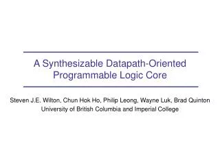
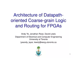
Architecture of Datapath-oriented Coarse-grain Logic and Routing for FPGAs Andy Ye, Jonathan Rose, David Lewis Department of Electrical and Computer Engineering University of Toronto {yeandy, jayar, lewis}@eecg.utoronto.ca
Outline • Motivation • Datapath regularity • An datapath-oriented FPGA • Architecture • CAD flow • Experimental results • Area efficiency • Conclusion
Modern FPGAs • Very large logic capacities • Over 10 million equivalent logic gates • Increasingly used to implement large and complex applications • Central processing units • Graphics accelerators • Digital signal processors • Packet switching networks
Datapath Circuits • Large applications • Contain a greater amount of datapath circuits • Datapath circuits • Consist of multiple identical logic structures called bit-slices • Regularity • Predictability
B0 C0 A0 C1 A1 B1 C2 A2 B2 B3 C3 A3 An Example Full Adder Full Adder Full Adder Full Adder Carry In Carry Out
Research Goal • Design a new FPGA architecture • Utilize datapath regularity • Reduce the implementation area of datapath circuits on FPGAs • Implement a full set of CAD tools for the new architecture • Synthesis • Packing • Placement • Routing
Key Architectural Features • A bus-oriented logic block architecture • A mixture of coarse-grain tracks and fine-grain routing tracks
L L L L L Logic Block S S Switch Block Coarse grain routing tracks Fine grain routing tracks Datapath FPGA Overview Routing Channels
BLE BLE BLE BLE BLE BLE BLE BLE BLE MUX LUT BLE BLE BLE BLE Local Routing Network BLE DFF BLE BLE BLE BLE BLE M BLE A Basic Logic Element (BLE) A Cluster Logic Block — Super-cluster Cluster 1 Cluster 2 Cluster 3 Cluster 4
L L L L L Super-cluster S S Switch Block Coarse grain routing tracks Fine grain routing tracks Datapath FPGA Overview Routing Channels
Super-cluster Cluster Cluster Cluster Cluster M Switch Block M M M M M Fine-grain Routing M Coarse-grain Routing Coarse-grain Routing Tracks
CAD Flow • CAD flow for the datapath-oriented FPGA consists of • Synthesis • Packing • Placement • Routing • Conventional CAD flow • Minimize area and delay metrics • Destroy datapath regularity
Datapath-oriented CAD Flow • Preserve datapath regularity (bit-sliced structures) • Map the preserved regularity onto the datapath-oriented FPGA architecture • Maximize the utilization of coarse-grain routing tracks • Minimize the implementation area of datapath structures
Datapath Representation • Datapath circuits are represent by netlists of datapath components (VHDL or Verilog) • Datapath component library • Multiplexers • Adders/subtracters • Shifters • Comparators • Registers • Each component consists of identical bit-slices
Synthesis • Enhanced module compaction algorithm • Based on the Synopsys FPGA compiler • Augmented with several datapath-oriented features • Preserve datapath regularity by preserving bit-slice boundaries • Achieve as good area results as the conventional synthesis tools
a3 a0 a2 b0 b3 b2 a1 b1 mux mux mux mux c2 c0 c3 c1 d3 d0 d2 d1 + + + + s2 s3 s0 s1 An Example Datapath Circuit sel cin cout
a0 b0 c0 sel 4-LUT cin d0 4-LUT + 4-LUT s0 Synthesis a0 b0 sel mux c0 d0 cin s0
a3 a2 a0 a1 b2 b0 b3 b1 c3 c1 c0 c2 sel sel sel sel 4-LUT 4-LUT 4-LUT 4-LUT cin d0 d1 d2 d3 4-LUT 4-LUT 4-LUT 4-LUT cout 4-LUT 4-LUT 4-LUT 4-LUT s0 s1 s2 s3 Synthesis
Packing • Based on the T-VPACK packing algorithm • Pack adjacent bit-slices into super-clusters • Utilize carry connections in super-clusters to minimize the delay of carry chains
An Example • Four clusters per super-cluster • Two BLEs per cluster • Six inputs per cluster BLE BLE BLE BLE BLE BLE BLE BLE
a0 a0 b0 b0 c0 c0 sel sel 4-LUT cin d0 4-LUT 4-LUT s0 Packing Into Clusters BLE BLE BLE d0 cin BLE BLE BLE BLE s0
a2 a1 a3 a0 b1 b3 b2 b0 c0 c1 c3 c2 sel sel sel sel Packing Into Super-clusters BLE BLE BLE BLE BLE BLE BLE BLE d0 cin d1 d2 d3 BLE BLE BLE BLE BLE BLE BLE BLE s0 s1 s2 s3 cout
Placement • Based on the VPR placer • Use simulated annealing algorithm • For super-clusters containing datapath circuits • Move super-clusters only • For super-clusters containing non-datapath circuits - Move individual clusters
Routing • Based on the VPR router • Use the path finder algorithm • As much as possible • Route buses through coarse-grain routing tracks • Route individual signals through fine-grain routing tracks • When necessary • Use coarse-grain routing tracks for individual signals • Use fine-grain routing tracks for buses
Area Efficiency • Benchmarks • 15 datapath circuits from the Pico-java processor • Architectural assumptions • Four BLEs per cluster • Four clusters per super-cluster • Four coarse-grain tracks sharing configuration memory • Logic track length of two • Disjoint switch block topology • Architectural variables • Number of coarse-grain tracks
Area Efficiency normalizedcircuit area circuit area in minimumtransistor area (x106) 100.0% 1.60 95.0% 1.50 90.0% 1.40 0% 0%- 10% 10%- 20% 20%- 30% 30%- 40% 40%- 50% 50%- 60% 60%- 70% % of coarse-grain tracks
Logic Track Length Vs. Area • Architectural assumptions • Four clusters per super-cluster • Four coarse-grain tracks share configuration memory • 50% of tracks are coarse-grain tracks • Disjoint switch block topology • Architectural variables • Number of BLEs per cluster • Logic track length
Logic Track Length Vs. Area circuit area inminimum transistor area (x106) N = 2 N = 4 2.20 N = 8 2.00 N = 10 1.80 track length 1.60 1 2 4 8 16
Conclusion • Proposed a datapath-oriented FPGA architecture and its CAD tools • Best area is achieved when • 40% - 50% of tracks are coarse-grain routing tracks • Four BLEs per cluster • Logic track length of two • Best area is 9.6% smaller than conventional FPGAs