Welding in Automation
Welding in Automation. Clint McKeachnie December 8, 2010. Definition. Cool Applications. There Are Four Popular Types Of Industrial Welding Robots Rectilinear Robots Articulating Robots Cylindrical Spherical.

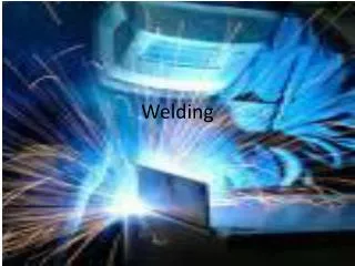
Welding in Automation
E N D
Presentation Transcript
Welding in Automation Clint McKeachnie December 8, 2010
Definition Cool Applications There Are Four Popular Types Of Industrial Welding Robots • Rectilinear Robots • Articulating Robots • Cylindrical • Spherical Rectilinear - Three axes (X, Y, Z), linear movement, and box shaped robotic working zone (EAAL lab) Articulating - Employ arms and rotating joints, move like a human arm, irregularly shaped working zone Cylindrically - Moves within a hollow cylinder The arm holding the welding torch moves up and down the mast, swings about the mast and extends and retracts Spherically (polar)- Moves within a hollow sphere. The mechanism holding the arm swings about its vertical .axis and rocks up and down about its horizontal axis.
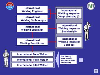
Where Are Welding Robots Used? Precision Laser Beam Welding Automotive Part Fabrication Aerospace Agriculture
Who, What, And When Are Welding Robots Used? • Gas metal arc welding (GMAW), commonly referred to as MIG • Tungsten inert gas arc welding (TIG) • Aluminum spool GMAW BYU’s Fanuc LR 200ic 5R 6 Axes robotic welder Powered by Lincoln welders Videos
Costs Robots – dependent on size, movement - Thousands! Tooling – dependent on fixtures - Thousands! Welders – dependent on Duty cycle and size - Thousands! Controls – dependent on tracing vision - Thousands! Full welding FMC – Millions! Flexible Manufacturing System (FMS)
Supporting Technology • Preview Sensing Joint Tracking Approach - Preview sensing is a joint tracking approach that generates information about the joint before it is welded. (contact type sensors such as mechanical probes) • Contact Sensing in Joint Tracking Systems -The contact style of sensor utilizes the joint preparation or part geometry as a mechanical guide • iRvision – Through vision systems, alignment, joint, and path recognition can be achieved. • Programming – Karel, V+ software, programmable logic controllers (PLCs), and application of C programming concepts, CAD/CAM • Control – Teach pendant, remote software driven, CAD/CAM head controllers, Most componies have there own teach pendant or controlled with their own program, and touch interface. Robot to MIG welder controlled.
Application Rules and Limitation • Adaptive Control Features - Programming can be done efficiently and with a minimal amount of formal training. The software should be designed such that 100% of the programming can be done at the teach pendant, utilizing a combination of dedicated function keys, software keys, and software menus tailored for arc welding. • Interfacing with Peripheral Equipment – Robotic arc welding has unique requirements for interfacing with peripheral equipment. A typical requires that the robot be interfaced with welding equipment, table positioning, cell controllers, and clamping & braking systems. • Dust-proof control enclosure - Air-to-air heat exchanger, as opposed to fans circulating shop air over the control components. • Control Hardware - The welding environment contains smoke, spatter, often, high ambient heat, and in some cases, RF (radio frequency) noise generated by GTAW arc starters and pulsation generators. • Degree of Freedom - Number of Axes • Drive System - For arc welding applications, electric drives require less maintenance and are more precise and less expensive than a comparable robot with hydraulic actuators. Considerations 1. Robot repeatability: ± 0.2 mm.2. Net reach: 800 mm (31.5 in.), minimum.3. Continuous path capability: ± t 0.4% continuity.4. Minimum continuous path velocity: 1000 mm/min (39.4 in.). Robot or Not?
Primary Vendors • Things to Remember With Vender Relations • Create vendor lists • Develop a request for quote (RFQ) • Solicit bids • Compare bids • Select a vendor • Keep relationships appropriate. • Don’t receive gifts or favors. • Give everyone the same information. • Don’t make promises until a final decision is made. • Always get at least two quotes to avoid appearance of conflict of interest. • Work through purchasing agent as much as possible. Especially with national venders MOTOMAN KUKA
Standards • Structure - Mostly vertical jointed-arm type some of the other types are used in industry. • Controlled Axes 4 - 8 When adding multiple axes tables • Repeatability ±0.08 mm (±0.003") Most welding beads have heat effected zones much larger than this. • Braking for slowing arm articulation velocity - Popular in all axes (improves the life of the machine) • Cooling System - Some have attachment chiller coolers, most areIndirect cooling. • Ambient Temperature During operation: 0° to 45° C (32° to 113° F) chillers recommended for < 113° F • Relative Humidity 90% max. non-condensing • Primary Power Requirements 3-phase, 240/480/575 VAC at 50/60 Hz • Digital I/O Standard I/O: 40 inputs/40 outputs consisting of 16 system inputs/ NPN-Standard 16 system outputs, 24 user inputs/24 user outputs PNP-Optional 32 Transistor Outputs; 8 Relay Outputs Max. I/O (optional): 2,048 inputs and 2,048 outputs • Position Feedback - Mostly all by absolute encoder • Program Memory JOB: 200,000 steps, 10,000 instructions CIO Ladder Standard: 15,000 steps Expanded: 20,000 steps • Interface - Compact Flash slots or USB port (1.1) • Pendant Playback & Buttons Teach/Play/Remote Key switch selector Servo On, Start, Hold, and Emergency Stop Buttons • Programming Language INFORM III, menu-driven programming • Maintenance Functions Displays troubleshooting for alarms, predicts reducer wear • Number of Robots/Axes Up to 8 robots, 72 axes with in modular or stationary cells • Multi Tasking Up to 16 concurrent jobs, 4 system jobs • Fieldbus DeviceNet Master/Slave, AB RIO, Profibus, Interbus-S, M-Net, CC Link, EtherNet IP/Slave • Ethernet 10 Base T/100 Base TX • Safety Dual-channel Emergency Stop Pushbuttons, multiple position Enable Switch, Manual Brake Releases Meets ANSI/RIA R15.06-1999, ANSI/RIA/ISO 10218-1-2007 and CSA Z434-03
Manufacturing Integration Most Important Engineers need to assure equipment and process compatibility to achieve ultimate success. The key areas to be analyzed are: 1. Parts selection and Processing. - Part design, Process design, Process Flow Maps, 6 sigma quality control tools, & LEAN2. Robot selection. - Make-buy diagrams, Investment Analysis, Procurement strategies, vender relations.3. Welding equipment selection. - The robot is the driver, inert gas, fixtures, Rotary tables, the welder, drive power supplies 4. Auxiliary equipment selection. - Support tooling, Shields, safety devises5. Facility requirements. - Power, Space, FMS cell layouts, Plant layouts, product flow layouts. 6. Operation activities. - Throughput, Takt times, Forecast calculations, WIP control, Raw material forecast, 7. Human factors. - Ergonomics - Health 8. Manufacturing capital factor. - This is all about making money, right?
References • http://www.io.com/~tcm/images/TWCLASF1.GIF • http://www.genesis-systems.com/weldinginnovation.com • http://www.fanucrobotics.com/ • http://www.abb.com/robots • http://www.motoman.com/ • http://www.robots.com/ • http://www.panasonicfa.com/ • http://www.kuka.com/ • http://daihen-usa.com/ • http://www.millerwelds.com/products/ • http://www.lincolnelectric.com/mig-welders.asp • http://www.deere.com/en_US/deerecom/usa_canada.html • http://www.boeing.com/
Summarize • Look at the hand out! • Things to look at from a Manufacturing Engineers point of view