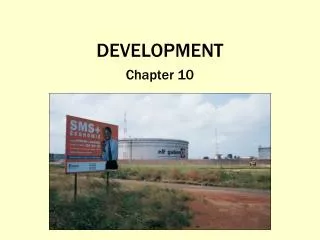
Development of the Eco-Friendly Pedibus Prototype for Sustainable Urban Tourism
The Pedibus project aims to create an eco-friendly, pedal-powered vehicle for city tours, attracting a diverse audience. Sponsored by Capital City Pedicab Company and in collaboration with FSU and FAMU College of Engineering, our team developed a fully operational prototype. The project included extensive research, design, manufacturing, and testing phases. The final design features a lightweight structural frame, efficient drive train, and comfortable seating, promoting a sustainable and enjoyable mode of urban transportation for all ages.

Development of the Eco-Friendly Pedibus Prototype for Sustainable Urban Tourism
E N D
Presentation Transcript
Pedibus Development April 17, 2014 Sponsored by Capital City Pedicab Company In affiliation with the FSU and FAMU College of Engineering Team 18: OnyewuchiEbere Andrew Galan John Hassler James McCord Sponsor: Instructor: Ron Goldstein Dr. Kamal Amin Faculty Advisors: Dr. Patrick Hollis
Executive Summary • The development of the Pedibus surrounded the idea to provide an eco-friendly and environmentally safe traveling entertainment vehicle to attract people of all ages and professions. • Our goal: Build and design a fully-operating pedibus prototype that will be used as a guide for future manufacturing, reproduction, and advertising purposes. • Throughout the past school year, the development has undergone a series of processes that included research, design, finance, analysis, manufacturing, and testing. • Overall Accomplishment: The fully-operating Pedibus prototype has been manufactured and tested for reliability, safety, and operation.
Needs Assessment • The task assigned by the sponsor, Ron Goldstein of Capital city Pedicabs, was to build an eco-friendly, pedal powered vehicle, to be used for tours and attractions throughout the city of Tallahassee. • Inspiration was provided by already exiting models, but not limited to a set configuration as the sponsor entrusted the design of the prototype to the team members. • The overall function of the Pedibus requires a comfortable cadence speed to power the central drive train based purely on pedal inertia.
Design Process • The structural design and dynamic analysis of the Pedibus prototype was the main focus during the fall semester. • The initial design and selection was broken down into three stages: • Structural Frame • Steering and Braking • Power Generation and Efficiency • Several designs were presented that allowed for a variation of models to be considered. The final design to be manufactured was decided by both the sponsor and the team members.
Structural Frame Selection The structural frame of the Pedibus depended on three main components. • Strength of material • The materials had to be strong enough to allow for minimal deflection and maximum stress when applied to heavy loads. • Weight of material • The weight of the material had to be light enough so the passengers could move the Pedibus with minimal effort. • Cost of the material • The cost played a large role in the selection process of the material. There was an initial ideal budget set that had to be followed which limited the selection of some materials.
Structural Frame Design • The structural frame was chosen to be made out of both aluminum and steel. • This combination of bottom steel supports and aluminum cross members promoted a weight reduction of about 260 lbs. in comparison to an all steel frame. • The aluminum cross members still provided enough stability and support to absorb the downward force produced by each individual passenger. • The cross members were attached to the steel support beams by custom made brackets that limited any potential movement.
Drive Train Design Selection Existing models use: • Cold rolled steel drive shaft • Rear axle from automobile • Differential from automobile Question How to connect pedals to drive shaft? John Hassler
Drive Train Layout • Chains on one side crossed • Crossed chains run through pulley • Bike gears and chains installed to the right of cross member from passengers perspective John Hassler
Peddling station Design • Design # 1 – Standard bicycle peddling station • Pros: • Higher viewing angle better for scenic tours • Seated at a table (more social, able to drink or eat) • Peddling is similar to traditional bike orientation • Cons: • Capable of generating less total power • less comfort on long rides due to lack of back support • Design # 2 – Recumbent peddling station • Pros: • Capable of generating more power per peddling station • Seating is comfortable for long periods of time • Cons: • Lower viewing angle • Seating is less conducive to social interaction • Smaller populace capable of powering the peddling station • Head is in unsafe position John Hassler
Steering and Braking Selection • Chose rack and pinion steering and hydraulic disc brakes early in the fall semester. • Entertained the idea of using a VW beetle front end to simplify the manufacturing process. • Ultimately decided on a mustang II independent front suspension kit that encompassed braking, steering, and suspension.
Final Design • The Pedibus will include: • 8 passenger pedaling stations. • 1 driver station located at the front • Manual rack and pinion steering • Front hydraulic disc brakes • Additional room for standing passengers. • An estimated maximum speed of 7 mph. • Independent front suspension • Adjustable seat and bar height • Easy maintenance • An enjoyable atmosphere
Encountered Problems • Due to the original storage space no longer being available, a new location had to be found. • The assembly is now being performed in the machine shop located on campus. • The front end suspension components that were delivered as a set did not configure with one another and thus delayed the installation process. • Overcoming the poor customer service by the company and with the assistance of the men in the machine shop, the front end was able to be assembled and welded to the frame. • The rear differential and steering also provided a delay in the current progress. • Alternative solutions have been found for both issues and have been resolved.
Structural Frame Design Changes • Finite Element Analysis performed on the structural frame only included forces related to static load. • The original analysis did not account for forces acting on the frame when the vehicle makes a hard stop, a passenger leans over, etc… • Added additional aluminum connecting all the crossmembers to add rigidity to the frame
Rear Differential Connection Design Changes • Original design required that spacers be placed between the rear axle and the steel supports so that the drive shaft would line up with the rear differential. • This caused issues with ground clearance and required meticulous placement so that the drive shaft lined up perfectly with the rear axle. • A high torque ujoint was used to correct the offset between the rear differential and the drive shaft.
Pedal crank design changes • As the pedibus is used the chains will stretch. • Some mechanism had to be included so the tension of the chain could be adjusted. • A new pedal crank design was chosen to make this possible.
Seat post collar design changes • The seat post collar went through many design iterations. • The final seat post collar was milled form a solid billet of aluminum. • It is the most meticulously machined part on the pedibus. Old Design New Design
Crossed Chain Separator Design Changes • The team tried several different separator designs. • Two separate pulleys • Single double pulleys • Derailleur gears • Nilon separator • There is difficulty keeping the chain on the sprocket when its angle of deflection is increased • Ultimately chose to use a delron block with guides cut out for both sides of the chain
Removal Of Front End Suspension • The company we ordered the mustang II IFS front end kit from took two months to ship us all the parts • After all the parts were shipped it was discovered that the shocks included with the kit were not the correct shocks. • Due to time constraints the suspension was removed and a threaded rod was bolted in place so assembly could proceed.
Steps In Assembly • Connected rear end to steel supports • Connected front end to steel supports • Attached aluminum cross members to steel supports • Assembled and attached bike parts • Assembled drive shaft and connected bike parts and rear differential • Installed walking platform • Installed brakes, steering, and driver seat • Installed handlebars
Future Recommendations • Use a cheaper commercial front end or design one. • A Mazda Miada front end has been recommended as a replacement for the Mustang II because of its simplicity and low cost. • Construct an all steel structural frame instead of a steel and aluminum combination. • The savings in weight were defeated by the increased complexity in manufacturing • Implement a method for changing gear ratio. • Max speed is currently limited by pedaling cadence not by power requirement. Andrew Galan
Conclusion • The design and construction of the Pedibus has taken the entire time provided by these last two semesters and required the removal of several desirable components. • Many of the original designs didn’t work and had to be redesigned. • The assembled pedibus prototype was a success with a top speed of ~5mph and can be powered by a single passenger. • We encourage Mr. Goldstein to bring the project back next year to add a power assist electric motor, lights, speakers, etc… • A special thank you to Jeremy Phillips. The machinist in the engineering school machine shop. Without Jeremy’s constant help and advice we would not have completed the project.
Future Demonstration • The assembly of the prototype is still under construction. Upon completion and after testing, the pedibus will be ready for demonstration. • Public demonstration will occur during the open house event hosted by the FSU Engineering department.