Download
1 / 21
210 likes | 382 Vues
AGENDA. Approval of agenda and minutes of last meeting Integration. L. Leistam (09.10-09.25) FMD design overview. JJG (09.25-09.50) Si-FMD Background simul. A. Maievskaia (09.50-10.15) Si-FMD FE and RO electronics. B.S.Nielsen (10.15-10.40) Coffee break

E N D
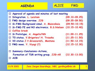
AGENDA • Approval of agenda and minutes of last meeting • Integration. L. Leistam (09.10-09.25) • FMD design overview. JJG (09.25-09.50) • Si-FMD Background simul. A. Maievskaia (09.50-10.15) • Si-FMD FE and RO electronics. B.S.Nielsen (10.15-10.40) • Coffee break • Si Prototype. A. Angelis/NN (11.00-11.25) • T0 status. V.Grigoriev/ H. Trzaska (11.25-11.50) • V0 status J.Y.Grossiord/L. Montano (11.50-12.15) • PMD news. Y. Viyogi (?) (12.15-12.30) • Summary-Conclusions-Actions, Formation of TDR writing group. JJG+All (12.30-13.00) • AOB Jens Jørgen Gaardhøje, NBI, gardhoje@nbi.dk
Si-FMD Freeze inner radius? Freeze general geometry. Integration with ITS and other FD Define Services (cables, cooling, etc.) Define Responsibilities, timetable Go to bids. Commence Prototyping. T0 Define final geometry (L,R) Trigger Timetable Go to prototyping V0 Design status Integration, trigger Prototyping. Organization Responsibilities TDR writing group formation Main issues Jens Jørgen Gaardhøje, NBI, gardhoje@nbi.dk
Overall Geometry • -5.4< <-1.6 • 3 < < 1.6 Si 4 Si3(moved) Si2 Si1 Jens Jørgen Gaardhøje, NBI, gardhoje@nbi.dk
Integration in ALICE Si-1 V0-R Si-2 T0-R Si-3 Jens Jørgen Gaardhøje, NBI, gardhoje@nbi.dk
Si1 with 6” Wafers Si 1 outer 2 Rings Si 1 inner Jens Jørgen Gaardhøje, NBI, gardhoje@nbi.dk
Si1 with 6” Wafers Outer Ring 24 R=35.1cm 16 24 R=22.1cm R=39.9cm 8 R=28.8cm R=17.1cm R=5.3cm 2 Rings Inner Ring Jens Jørgen Gaardhøje, NBI, gardhoje@nbi.dk
Ring geometry !!30 cm vertex shift: 1.2 Jens Jørgen Gaardhøje, NBI, gardhoje@nbi.dk
Background and acceptance Pseudorapidity coverage • Si1 & Si2 (inner and outer) d(IR)=62.8 and 75.8 cm: 1.51 <||< 1.94 2.03 <||< 3.58 • Si3: d(IR)345cm -5.28 << -3.71 • Vertex shift (30cm): |d| 0.3 Jens Jørgen Gaardhøje, NBI, gardhoje@nbi.dk
Background simulationsAlla Maevskaia Jens Jørgen Gaardhøje, NBI, gardhoje@nbi.dk
Background simulationsAlla Maevskaia Jens Jørgen Gaardhøje, NBI, gardhoje@nbi.dk
Background simulationsAlla Maevskaia Jens Jørgen Gaardhøje, NBI, gardhoje@nbi.dk
Background simulationsAlla Maevskaia Jens Jørgen Gaardhøje, NBI, gardhoje@nbi.dk
RHIC vs. LHC BRAHMS @ RHIC 200 • RHIC (s=130 AGeV): -5 << 5 Plateau: –2 << 2 (40% of range) dN/d(=0)=550. (s=200 AGeV): -6 << 6 dN/d(=0)=610. Nch =5100 • LHC (s=5800 AGeV): -9 << 9 BRAHMS 200AGEV Jens Jørgen Gaardhøje, NBI, gardhoje@nbi.dk
SPS Limiting particle prod. in fragmentation region • RHIC: saturation of particle production in fragmentation region is already achieved at SPS. • Width of Frag. Region is 3. • LHC: = (–9,+9) • RHIC200: = (–6,+6). • May expect that central region at LHC extends to –(6,+6). • Si-FMD and V0 detectors cover (-1.5,5.3), i.e. interesting region. BRAHMS: RHIC 200. Prelim BRAHMS. Subm. to Phys Lett. B. 2001 Jens Jørgen Gaardhøje, NBI, gardhoje@nbi.dk
Physics and rates Central Pb+Pb : Nch(Si) 15.000-20.000 p+p Nch(Si) 50-100 Pb+Pb 8kHz. (1kHz central) Average event spacing >100s p+p up to 1 coll/bunch crossing Average event spacing 25 ns WHO does it? LVL0 Timing: T0 Vertex ( 1-2 cm) T0 Vertex ( 0.1-0.2 cm) TPC Rough on-line Centrality cut on dE V0 p+p trigger V0 Timing+vertex(p+p) T0,V0 Precise centrality Si Fluctuations Si Azimuthal distribution Si Off-Line PID (dE) Si Level 0 T0,V0 Off-line, Higher level Si Si-FMD Role in Trigger Jens Jørgen Gaardhøje, NBI, gardhoje@nbi.dk
Electronics overview • Assume 128 strips/wafer • Assume 32 channels/chip • Assume 8 chips/RO card Jens Jørgen Gaardhøje, NBI, gardhoje@nbi.dk
Cost Estimate • VERY uncertain and preliminary estimate in CHF. • 6”Ø: still experimental • Test production batch: 16-25 wafers Jens Jørgen Gaardhøje, NBI, gardhoje@nbi.dk
Item Status Est. completion date Comments Overall system design Ongoing July 2001 Choice of RO electronics Ongoing September 2001 exploration Procure Test wafers October 2001 Needs industry survey Procure test RO electr. October 2001 Mechanical design and integration in ALICE Ongoing December 2001 Assembly test detector March 2002 Tests with sources/beam March 2003 Final design June 2003 Procure full Si and FE June 2003 Manufacture mechanics December 2003 Delivery February 2004 Assembly full system October 2004 Installation in ALICE June 2005 First p+p runs August 2006 First A+A runs Spring 2007 Si-FMD Timetable . Jens Jørgen Gaardhøje, NBI, gardhoje@nbi.dk
TASKS Update geometry and integration drawings Update simulations of background, resolution and performance Choice of electronics Tender and order prototype 6” wafers Construct and test FE+RO system Test DAQ and integrate with DAQ Update prelim-TDR-started PPR- needs to develop WHO? NBI INR NBI NBI NBI + ? ? NBI, INR, Athens, ? Responsibilities Si-FMD Jens Jørgen Gaardhøje, NBI, gardhoje@nbi.dk
TASK T0 Tech. Design study T0- technology decision and funding T0 prototyping V0 TDR Prototyping Who? MEPHI and Jyvaskyla ” ” Lyon and Mexico Responsibilities T0 & V0 Jens Jørgen Gaardhøje, NBI, gardhoje@nbi.dk
Si-FMD acceptance downscoped to -5.28 < < -3.71 1.51 < < 3.58 Background from beam pipe important-> redesign needs to be pursued Si-FMD not present in trigger at LVL0. Analog sum trigger for LVL1 seems possible but not likely. FEE /(ampl. Chip. Hybrid, ADC, receiver) can be developed together with IDEAS-Norway. Revisit segmentation for flow analysis T0 ismain Alice timing trigger Two arm necessary for good vertex also in absence of TPC and pixels Radiator-PM is baseline design Two-arm V0 for beam gas-rejection V0 ismain Alice centrality trigger Integrate Si3, T0(L), V0(L) and PMD Endorsed Recommendation to ALICE Forum,TB,MB,CB Jens Jørgen Gaardhøje, NBI, gardhoje@nbi.dk


