Download

1 / 19
190 likes | 420 Vues
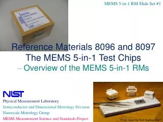
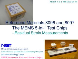
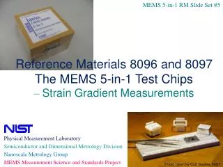
MEMS 5-in-1 RM Slide Set #6. Reference Materials 8096 and 8097 The MEMS 5-in-1 Test Chips – Step Height Measurements. Physical Measurement Laboratory Semiconductor and Dimensional Metrology Division Nanoscale Metrology Group MEMS Measurement Science and Standards Project.

E N D
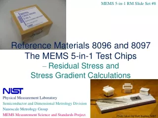
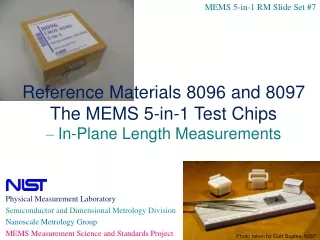
MEMS 5-in-1 RM Slide Set #6 Reference Materials 8096 and 8097 The MEMS 5-in-1 Test Chips – Step Height Measurements Physical Measurement Laboratory Semiconductor and Dimensional Metrology Division Nanoscale Metrology Group MEMS Measurement Science and Standards Project Photo taken by Curt Suplee, NIST
Outline for Step Height Measurements
1. References to Consult • Overview 1. J. Cassard, J. Geist, and J. Kramar, “Reference Materials 8096 and 8097 – The Microelectromechanical Systems 5-in-1 Reference Materials: Homogeneous and Stable,” More-Than-Moore Issue of ECS Transactions, Vol. 61, May 2014. 2. J. Cassard, J. Geist, C. McGray, R. A. Allen, M. Afridi, B. Nablo, M. Gaitan, and D. G. Seiler, “The MEMS 5-in-1 Test Chips (Reference Materials 8096 and 8097),” Frontiers of Characterization and Metrology for Nanoelectronics: 2013, NIST, Gaithersburg, MD, March 25-28, 2013, pp. 179-182. 3. J. Cassard, J. Geist, M. Gaitan, and D. G. Seiler, “The MEMS 5-in-1 Reference Materials (RM 8096 and 8097),” Proceedings of the 2012 International Conference on Microelectronic Test Structures, ICMTS 2012, San Diego, CA, pp. 211-216, March 21, 2012. • User’s guide (Section 5, pp. 96-113) 4. J.M. Cassard, J. Geist, T.V. Vorburger, D.T. Read, M. Gaitan, and D.G. Seiler, “Standard Reference Materials: User’s Guide for RM 8096 and 8097: The MEMS 5-in-1, 2013 Edition,” NIST SP 260-177, February 2013 (http://dx.doi.org/10.6028/NIST.SP.260-177). • Standard 5. SEMI MS2-1113, “Test Method for Step Height Measurements of Thin Films,” November 2013. (Visit http://www.semi.org for ordering information.) • Fabrication 6. The RM 8096 chips were fabricated through MOSIS on the 1.5 µm On Semiconductor (formerly AMIS) CMOS process. The URL for the MOSIS website is http://www.mosis.com. The bulk-micromachining was performed at NIST. 7. The RM 8097 chips were fabricated at MEMSCAP using MUMPs-Plus! (PolyMUMPs with a backside etch). The URL for the MEMSCAP website is http://www.memscap.com.
2a. Step Height Overview • Definition: The distance in the z-direction between an initial, flat surface and a final, flat surface • Purpose: To determine the thin film thickness values, which can be used in the determination of thin film material parameters, such as Young’s modulus • Test structure: Step height test structure • Instrument: Interferometric microscope or comparable instrument • Method: Obtained from multiple measurements taken along the width of a step height test structure z x
2b. Step Height Equation (for one trace) where stepNXYtstep height measurement from trace “t” stepNXYaverage of the step height measurements platNYtheight measurement of platform “Y” from trace “t” platNXtheight measurement of platform “X” from trace “t” calzz-calibration factor
2c. Data Sheet Uncertainty Equations • Step height combined standard uncertainty, ucSH, equation where uLstepdue to measurement uncertainty across length of step uWstepdue to measurement uncertainty across width of step ucertdue to the uncertainty of the value of the step height standard used for calibration ucaldue to the uncertainty of the measurements taken across the step height standard urepeat(shs)due to repeatability of measurements taken on step height standard udriftdue to the amount of drift during the data session ulineardue to the deviation from linearity of the data scan urepeat(samp)due to the repeatability of similar step height measurements
2c. Data Sheet Uncertainty Equations • The data sheet (DS) expanded uncertainty equation is where k=2 is used to approximate a 95 % level of confidence
2d. ROI Uncertainty Equation UROI expanded uncertainty recorded on the Report of Investigation (ROI) UDS expanded uncertainty as obtained from the data sheet (DS) Ustability stability expanded uncertainty
3. Location of Structure on RM Chip (The 2 Types of Chips) • RM 8097 • Fabricated using a polysilicon multi-user surface-micromachining MEMS process with a backside etch • Material properties of the first or second polysilicon layer are reported • Chip dimensions: 1 cm x 1 cm • RM 8096 • Fabricated on a multi-user 1.5 µm CMOS process followed by a bulk-micromachining etch • Material properties of the composite oxide layer are reported • Chip dimensions: 4600 µm x 4700 µm Lot 95 Lot 98
3a. Location of Structure on RM 8096 Top view of a step height test structure Locate the step height test structure in this group given the information on the NIST-supplied data sheet
3b. Location of Structure on RM 8097 Top view of a step height test structure Locate the step height test structure in this group given the information on the NIST-supplied data sheet
4a. Step Height Test Structure (For RM 8096) Top view of a step height test structure Cross section along Trace a, b, or c
4b. Step Height Test Structure (For RM 8097) Top view of a step height test structure Cross section along Trace a, b, or c
5. Calibration Procedure • Calibrate instrument in the z-direction • Before the data session • Record height of step height standard at 6 locations = mean value of the 6 measurements before= standard deviation of the 6 measurements • Record height of step height standard at same location for 6 measurements = mean value of the 6 measurements same1= standard deviation of the 6 measurements • After the data session • Record height of step height standard at 6 locations = mean value of the 6 measurements after= standard deviation of the 6 measurements • Record height of step height standard at same location for 6 measurements = mean value of the 6 measurements same2= standard deviation of the 6 measurements
5. Calibration Procedure (continued) • Determine the following: 1. 2. 3. 4. 5. 6. 7. cert = certified value of the step height standard if , then and if , then and if , then and if , then and • Supply the following inputs to the data sheet: • cert, cert • 6ave, • 6same, • zdrift, calz, and zlin cert = certified uncertainty of the step height standard zlin = maximum relative deviation from linearity over the total scan range of the instrument
6. Measurement Procedure • Obtain 3 2D data traces • Obtain the platform heights (and standard deviations) from each 2D data trace All measurements are with respect to the height of the reference platform (used to level and zero the data) (for one trace)
7. Using the Data Sheet • Find Data Sheet SH.1.a • On the MEMS Calculator website (Standard Reference Database 166) accessible via the NIST Data Gateway (http://srdata.nist.gov/gateway/) with the keyword “MEMS Calculator” • Note the symbol next to this data sheet. This symbol denotes items used with the MEMS 5-in-1 RMs. • Using Data Sheet SH.1.a • Click “Reset this form” • Supply INPUTS to Tables 1 and 2 • Click “Calculate and Verify” • At the bottom of the data sheet, make sure all the pertinent boxes say “ok.” If a pertinent box says “wait,” address the issue and “recalculate.” • Compare both the inputs and outputs with the NIST-supplied values
8. Using the MEMS 5-in-1To Verify Step Height Measurements • If your criterion for acceptance is: where DSH positive difference between the step height value of the customer, step1AB(customer), and that appearing on the ROI, step1AB USH(customer) step height expanded uncertainty of the customer USH step height expanded uncertainty on the ROI, UROI • Then can assume measuring step height according to SEMI MS2 according to your criterion for acceptance if: • Criteria above satisfied and • No pertinent “wait” statements at the bottom of your Data Sheet SH.1.a