3-D Viewing and Modeling Coordinates - CS-321 Dr. Mark L. Hornick
Learn about 3-D viewing and modeling coordinates, transformation, projection, and coordinate systems from the expert, Dr. Mark L. Hornick in CS-321. Understand how to identify viewer position relative to the scene, work with viewing and projection coordinates, and transform between different coordinate systems. Explore view-to-model and model-to-view transformations, as well as view-to-device and model-to-device transformations. Gain insights into changing views and coordinate frames in 3-D modeling and viewing.

3-D Viewing and Modeling Coordinates - CS-321 Dr. Mark L. Hornick
E N D
Presentation Transcript
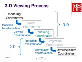
3-D Viewing Process ModelingCoordinates WorldCoordinates 3-D Modeling transformation Viewing transformation ViewingCoordinates Projection transformation ProjectionCoordinates 2-D Workstation transformation Device/WindowCoordinates CS-321Dr. Mark L. Hornick
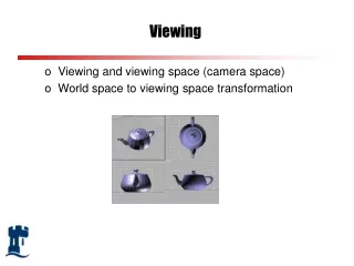
Viewing Coordinate System Identify viewer position relative to scene Viewer “looks through” a window Must specify position and view direction CS-321Dr. Mark L. Hornick
yv ym xv zv N xm zm View Plane View plane defined by normal vector (N) CS-321Dr. Mark L. Hornick
yv ym Pr P0 xv zv xm N zm View Reference Points • Pr: a point in the scene we are looking at • P0: a vantage point from which we’re looking • Note Pr, P0, and N are expressed in xmymzm CS-321Dr. Mark L. Hornick
ym ym xm xm zm zm Look-Up Vector V V View-plane normal vector and reference point are not enough We also need to specify orientation of view(er) View-up vector (V) must be normal to N CS-321Dr. Mark L. Hornick
yv P0 ym xv zv N xm zm Viewing Coordinates N,V form a right hand system. V Pr Viewing coordinate system based on vectors V,N Forms the (xv, yv, zv) coordinate axes CS-321Dr. Mark L. Hornick
yv P0 ym xv zv N,n xm zm Viewing Coordinates l,m,n form a right hand system. L,l m V Pr Note V and m are not necessarily parallel. CS-321Dr. Mark L. Hornick
ym Pr xm zm Changing Views (1) Maintain Pr, change N N N N CS-321Dr. Mark L. Hornick
zm N P0 Changing Views (2) Maintain N, change Pr and P0 Pr ym Pr Pr xm N N P0 P0 CS-321Dr. Mark L. Hornick
View to Model Transformation • Expresses the position & orientation of xvyvzv with respect to xmymvm • Allows us to transform coordinates from view frame to model frame • But we want just the opposite… CS-321Dr. Mark L. Hornick
Model to View Transformation • The inverse of the view to model transformation produces the model to view transformation • Expresses the position & orientation of xmymzm with respect to xvyvvv • Allows us to transform coordinates from model frame to view frame CS-321Dr. Mark L. Hornick
View to Device Transformation • The view to device transformation expresses the position and orientation of the view coordinate system w.r.t. the device coordinate system. • Allows us to transform coordinates from view frame to device/window frame. • Incorporates parameters that specify the offset of the view frame w.r.t. the upper-left corner of the screen, as well as the fact that the view frame is rotated 180 about the x-axis w.r.t. the device frame. CS-321Dr. Mark L. Hornick
Model to Device Transformation • The model to device transformation expresses the position and orientation of the model coordinate system w.r.t. the device coordinate system • This is simply the compound transformation of model to view, followed by view to device CS-321Dr. Mark L. Hornick
Model Coordinates to Device Coordinates • Using the compound model to device transformation, the coordinates of a point v in the model coordinate frame can be transformed into coordinates in the device/window frame • Scaling factor s can also be applied via a 3-D scaling matrix S CS-321Dr. Mark L. Hornick