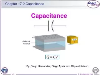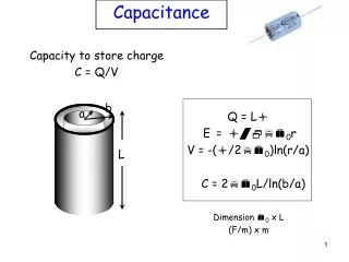
CPC2 Capacitance measurements
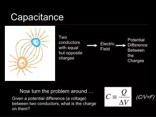
CPC2 Capacitance measurements. Erik Devetak -University of Oxford - (28-03-06) Outline: Capacitance of a CCD Inter-gate and substrate Capacitance Study of the depleted region. Gate. V ref. n+. Gate depletion. n. Junction depletion. p. n- p junction. p+.

CPC2 Capacitance measurements
E N D
Presentation Transcript
CPC2 Capacitance measurements Erik Devetak -University of Oxford - (28-03-06) Outline: Capacitance of a CCD Inter-gate and substrate Capacitance Study of the depleted region
Gate V ref n+ Gate depletion n Junction depletion p n- p junction p+ The Capacitance Measurements V Gate • C-Inter Gate depends on gap between gates. Expect no dependence on VRef • C-Substrate depends on depletion region. Expect: • When we increase VRef we increase the Junction and the Gate depletion length • When we increase VGate we increase the Gate depletion length and displace the Junction depletion • Once the Junction and the Gate depletion regions meet the capacitance will be independent on VRef, but still dependent on VGate
CCD Model Below we can see a simpleCircuit model of the CCD The arrows display the performed capacitance measurements A B A Cig Cig C sub C sub C sub C sub C C AB (ig measured) C AC (sub measured) From these values one can back calculate Cig and Csub
C vs. Vref Calculated Intra gate capacitance: 22 nF or 2.8 pF/cm of gate overlap or 2.8 nF/cm2 Calculated Sub. capacitance: 6 nF or 0.8 pF/cm of gate overlap or 0.8 nF/cm2 (f =60kHz ) Cig has a structure at 5-8 V, likely related to depletion of Buried Channel
1/C vs. Vref • 1/C proportional to depletion region • Capacitance saturates when the Buried Channel is depleted • Depleted region increases with VGate • Interesting features: -Non linear steps with respect to VGate -Breakdown at high voltage, possibly due to inversion under gates (f =80kHz )
Gate A Bc Sc Gate B CSub vs. VGate • Note large variations of CSub at negative VGate • The Capacitance derives from two different capacitances in parallel: • Surface Channel ( MOS – C ) • Buried Channel • Shape at negative VGate is driven by the Surface Channel capacitance • Model: (f =80kHz )
Depletion length calculation We can calculate the approximate depletion length by using the simple formula: At V Gate = 0 V For 1/C = 0.16 1/(nF) xd= 12.3 μm At V Gate = 10 V For 1/C = 0.20 (1/nF) xd= 15.4 μm Gain in additional depletion is small: ~25%
Conclusion • The C-V behaviour of the CCD has been tested and in general it behaves as expected • We measured an inter gate capacitance of 2.8 nF/cm of gate overlap length which is substantially higher than the one quoted from e2V (1.5 nF/cm ) and the one deriving from the simulation models ( 2.2 nF/cm ), but consistent with previous measurements • We also measured the maximum depletion length of the substrate at different reference and Gate Voltages (15.4 μm at Vref >11, VGate > 10 )