Download
1 / 22
220 likes | 370 Vues
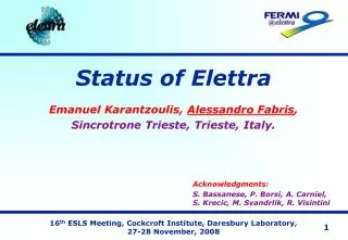
Impedance evolution and collective effects at Elettra Emanuel Karantzoulis. Elettra: what and where. Elettra is a 3rd generation Synchrotron light source at Trieste, Italy In operation for users since 1994. Configuration and Operational summary. Up to 2007. Since 2008.

E N D
Impedance evolution and collective effects at Elettra Emanuel Karantzoulis
Elettra: what and where Elettra is a 3rd generation Synchrotron light source at Trieste, Italy In operation for users since 1994
Configuration and Operational summary Up to 2007 Since 2008 0.9 GeV (accelerator physics time) for SR-FEL single bunch
operational developments For general diagnostic “SynchRobot” in collaboration with R. Pugliese and the scientific calculus for the programming Programmable and autonomous can perform measurements and other actions in hazardous (radiation) environments
Introduction 1mA at Elettra corresponds to • Understanding wake fields and impedances is of great importance for the design and performance of accelerators since instabilities driven by the beam wakes can very much limit the performance in both beam intensity and quality. • At Elettra there has always been a strong activity concerning wake fields, including also many measurements and observation on the storage ring like the impedance evolution with the addition of many low vertical gap vacuum chambers or the impedance increase due NEG coated chambers. • To this extend we also have collaborated with other labs (ESRF, SOLEIL ) and remote measurements using grid technologies have been also performed! • Lately much work was again up for the FERMI@Elettra FEL, connected to resistive wall/geometric/ surface roughness effects at very short bunches that can deteriorate the laser efficiency via instabilities like the micro-bunching instability
FERMI@Elettra E-beam Transport Systems Surface Roughness Wakefields Wakefields Induced Energy Spread in the FERMI Undulator Resistive wall Wakefields (circular, rectangular and elliptic vacuum chamber) Estimated energy spread for the FERMI FEL undulator 0.8 nC • In-house measurements • aluminum samples were cut from an elliptical vacuum chamber Atomic Force Microscope (AFM) was used C. Bontoiu and P. Craievich Elettra – Trieste A. Lutman and R. Vescovo Universita degli Studi di Trieste -DEEI C. Bontoiu, P. Craievich, L. Rumiz, L. Casalis Elettra – Trieste M. Castronovo Universitadegli Studi di Trieste
References • E. Karantzoulis, ”The Coupling Impedance of the Elettra Storage Ring”, Sincrotrone Trieste internal report, ST/M-TN-90/14, 1990 • E. Karantzoulis, C. J. Bocchetta, F. Iazzourene, R. Nagaoka, L. Tosi, R. P. Walker, and A. Wrulich, in Proceedings of the EPAC-94, London (World Scientific, Singapore, 1994) • B.W. Zotter and S.A. Kheifets , “ Impedances and Wakes in High-Energy Particle Accelerators”, World Scientific, 2000; • M. Svandrlik, “ Curing HOM driven coupled bunch instabilities at ELETTRA”, Talk given at Beam Instability Workshop – ESRF, Grenoble 13-15 March 2000 • J. L. Revol, R. Nagaoka, P. Kernel, E. Karantzoulisand L. Tosi, “Comparison of Transverse Single Bunch Instabilities between the ESRF and ELETTRA”, EPAC 2000, Vienna 26-30 June 2000 • E.Karantzoulis, V. Smaluk and L.Tosi,”Broadband Impedance measurements on the electron storage ring ELETTRA”, Phys. Rev. ST-AB, Vol. 6, 030703 (2003); • Effective Impedance Measurement at ELETTRA and Characterisation of NEG Coating In Term of Impedance.ESRF Technical note, Theory no 05-04 etc (series), S. Di Mitri(Elettra), L. Farvacque (ESRF), F. Iazzourene (Elettra) E. Karantzoulis (ELETTRA), R. Nagaoka (SOLEIL), T. Perron (ESRF) • G.Penco, C.Bontoiu, P.Craievich, E. Karantzoulis, V. Forchì, “Review of the longitudinal impedance budget of the ELETTRA storage ring”, PAC2007. • E. Karantzoulis, M. Lonza,” Transverse head-tail modes elimination with negative chromaticity and the transverse multi-bunch feedback system at Elettra” EPAc 2006, Edinburg,Scotland 26-30 June, 2006 • L. Tosi,V. Smaluk, and E. Karantzoulis,” Landau damping via the harmonic sextupole”, Phys. Rev. ST-AB, Vol. 6, 054401 (2003);
Early Situation • Single bunch was tried in 1994 and more than 60 mA @ 1GeV were stored on May 7th whereas at the same day were obtained 530 mA in 80% multibunch filling; the maximum reached was 700 mA (3 years later) and no injection saturation effects were observed! • These results show that special care was taken to have the impedance of the machine as low as possible. With the exception of the rf-cavities, the vacuum chamber (shape and material) with its connections, holes, steps etc. is the other important contributor of impedance. The vacuum chamber was made of stainless steel with dimensions 81x56 mm while at insertions had initially 76x20 mm (full horizontal x vertical ). The cavities are four copper single cells of a smooth bell shape. • Impedance budget calculations using mostly analytic formulae estimated that the broad band longitudinal impedance should be < 0.7 ohm while the transverse effective < 20 kohm /m Those predictions were in agreement with single bunch measurements shown that the longitudinal broad band impedance was ~ 0.2-0.5 ohm and the transverse effective ≤ 10 kohm /m. These values confirm also the theoretically predicted high current thresholds of ELETTRA.
Instability situation in 1994 • Mutibunch instabilities: existed as predicted, generated by the HOMs of the rf cavities. Four Elettra type single cell cavities are used and as usually are the biggest contributors to the machine impedance. Careful tuning of the cavity volume (via temperature control ) shifts the HOMs from the beam harmonics. A complete instability free condition at 150 mA was achieved while above the 150 mA it is still possible but more difficult. Nowadays MT(L)FB systems and a 3rd harmonic cavity help to eliminate all modes. • Resistive wall: was not observed up to 330 mA and assuming that it was Landau damped due to the (measured) incoherent betatron frequency spread f of about 160 Hz confirms again the low value of the impedance. • Head tail and mode coupling : Simple threshold estimations with the measured impedance set the threshold at 58 mA (1 GeV) but 65 mA were injected without saturation, however above 50 mA the beam was blown up and throbbing clearly indicating a threshold. The m=0 mode for small positive chromaticity was stable. At much higher currents ≥35 mA the m = -1,1 were also seen but no mode merging occurred. With slightly negative chromaticity the m = 0 threshold was found at ~22 mA above which the beam blew up vertically and oscillated again confirming the measurements
Impedance evolution Measurements of tune shift with sb current. The Im(ZTeff) can then be extracted from the known formula: giving 10 kohm/m for the starting value and 10-15 koh/m for each low gap chamber
Low gap chamber contribution include resistive wall, tapers and the NEG (T, Zr, V) It appeared as if every low gap chamber contributed as much as the whole 1994 machine and furthermore the NEG was adding as much!
Further developments During 2003/4 series of measurements in collaboration with ESRF and SOLEIL based on the bump method (T. Perron et. al.) tried understand the NEG puzzle but without a clear answer since theory predicts ~ 10 -15Kohm/m the rest could be attributed to bad rf-fingers / surface roughness/ thicker NEG
Mode coupling • Mode coupling. The mode m = 0 and m = -1 merging at 40 mA/bunch was seen with nearly zero chromaticity. • (ESRF - ELETTRA collaboration 2000). The situation after some more Neg chambers in 2003 was as follows: Y0=228-1.26x Y-1=215-0.56x ~ 18 mA Y0=210-1.49x Y-1=196-0.48x ~ 14 mA
Resistive part - 2003 • Beam interaction with a resistive transverse impedance results in the well -known head-tail instability characterized by the head-tail phase. For various beam currents, the damping rates were estimated by an analysis of the turn-by-turn beam positions whereas coherent betatron oscillations were excited by the TMFB system.On the basis of these measurements, the resistive part of the transverse impedance resulted to be ReZ = 0.160.05 M/m. Coherent head-tail damping
Longitudinal Impedance 2003 • An electron beam passing through irregularities of the vacuum chamber loses energy. The total energy loss DE is proportional to the square of the beam charge q The measurement was based on the indirect measurement of the beam energy loss using the standard BPM system (with multiplexing), the longitudinal loss factor k|| can be estimated by measuring the horizontal closed orbit deviation with the beam intensity Re(Z/n)=0.210.04 Ohm
Microwave limit • Bunch length measurements have been performed since the beginning using fast oscilloscopes, photodiodes and finally a streak camera to monitor also the effective longitudinal broad band impedance which can be obtained directly from measurements of the bunch lengthening using the microwave limit |Z/n|eff=0.32 0.06 ohm
2007 • New measurements with standard bpms and libera electronics were performed in 2007 In 4-bunch mode K|| is higher showing the dominance of localized narrow band structures like rf-cavities
Scraper impedance • In ELETTRA the vertical scraper is discontinuous and is composed of two 1 cm in diameter rods positioned at 25 mm when it is open. Analytical formulas for the impedance of such a geometry do not exist and evaluation of its behavior has been performed using the electron beam. To increase the accuracy, a variant of the bump method was used with the scraper slit vertically shifted instead of the orbit bump. The method with some limitations can be used for such an asymmetrical structure as the scraper. The closed orbit deviation proportional to the impedance and to the scraper blade position was measured using the BPM system
Scraper Impedance fitting • At 5 mm gap the reactive impedance is about 30 kohm/m h rod diameter d= max. half gap (25 mm ) One sees that the rods behave more like a tapered device (1/x ) instead of a step scraper (1/x2)
Negative chromaticity • Nowadays single bunch current is mode coupling limited at most 10 mA by m=0,-1 head tail modes. TFB cannot be used since can not detect/correct them. So the idea is to go to negative chromaticity where m=-1 mode is stable and cure with the TFB the m=0 mode The m=0 and m=-1 mode merging with positive chromaticity (0.4, 0.1), feedback on and kickers on, vertical plane The m=0 mode shift with vertical negative chromaticity (0,-2) feedback on and kickers on An accumulated current of 15 mA was achieved but not systematically. Much depends upon the machine and feedback fine settings. Nevertheless operating with negative chromaticity in the single or 4 bunch mode, even when higher thresholds could not be reached, the beam was very stable at all reached currents whereas when at positive chromaticity the beam started becoming sometimes unstable after 7 mA.
Conclusions • Muti-bunch instabilities did not change behavior. In fact for many years almost the same cavity temperature settings are used. Using TMFB and the 3rd harmonic cavity result in efficient elimination of any multibunch instabilities. A LMFB also exists but not in use. • Mode coupling. The mode m = 0 and m = -1 merging at 12 mA/bunch with nearly zero chromaticities. Head-tail instabilities: with slightly positive chromaticity no more than 5 mA can be stored. Increasing the chromaticity some 8 mA/bunch can be reached at 1 GeV. At 2 Gev however things are better, 10 mA/bunch are stable at near zero chromaticity. • Thus only the few bunch operations at low energies were affected but this is critical since at 1 GeV operates the SR-FEL However since it is using seeding 5mA/bunch are more that enough, usually operates at 1mA/bunch! Experimentalists requests compromise the machine! For 2010 two low gap (9 mm vertical) NEG chambers are to be installed replacing NEG 14 mm ones!-> life continues being interesting