Download

1 / 5
50 likes | 156 Vues
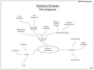
This document outlines the magnetic measurements and modeling of the MICE target stator, presented by Ben Shepherd at the MICE target workshop on May 13, 2011. It covers the initial setup and alignment of the stator with a precision of ~100μm over 1.8m. A detailed measurement technique utilizing a 3-axis Hall probe for field mapping in 2D and 3D models is described. Key results include the determination of solenoid axis through field observations, including the identification of minimum values in B2 and zero in B0 and B1.

E N D
MICE target stator:measurements & modelling Ben Shepherd MICE target workshop 13 May 2011
Talk Outline • Magnetic measurements of target stator • setup & alignment • measurement technique • position of centre • Modelling of stator & magnets • 2d model • 3d model
Measurement Setup • Stator set up on magnet measurement bench at Daresbury • Aligned to ~100µm in 1.8m • Measure field using 3-axis Hall probe, movable in 3 directions telescope Hall probe bench x y z
Longitudinal field map • B0, B1: transverse field • B2: longitudinal field • To find solenoid axis: minimum in B2, zero in B0, B1