Mechanics:
Mechanics: a branch of physics that is concerned with the motion and deformation of bodies in response to forces Applied (or Engineering) Mechanics: the science of applying the principles of mechanics. Rigid Body Mech. Statics. Dynamics. Kinematics and Kinetics. Deformable Body Mech.

Mechanics:
E N D
Presentation Transcript
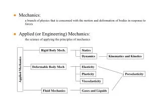
Mechanics: • a branch of physics that is concerned with the motion and deformation of bodies in response to forces • Applied (or Engineering) Mechanics: • the science of applying the principles of mechanics Rigid Body Mech. Statics Dynamics Kinematics and Kinetics Deformable Body Mech Elasticity Applied Mechanics Plasticity Poroelasticity Viscoelasticity Fluid Mechanics Gases and Liquids
Physical Properties of Spinal Elements • Spinal Elements: • Bone • Vertebral body: Cortical bone, cancellous bone, and bony endplate • Posterior bony elements • Soft Tissues • Ligaments and intervertebral disc • Physical Properties: • Mass: • Bone density • Mass moment of inertia for dynamic analysis • Morphology: • Structure, shape, size, location, area and polar moment of inertia • Mechanical (Elastic, elastic, and poroelastic) Properties: • Stiffness: compression, tension, share, bending, torsion • Moduli and Poisson’s ratio • Permeability
Measurement of Physical Properties • Mass Measurement: • Direct measurement • Dual X-ray Absorption metry for BMD measurement • QCT • Morphology Measurement: • Direct measurement from cadaveric specimens • Video system • Plain X-rays • CT and MRI • Mechanical Properties • Elastic Property Measurement: • Static mechanical tests in compression, tension, shear, bending and torsion tests • Viscoelastic Property measurement: • Creep, relaxation, cyclic loading tests • Poroelastic Property Measurement: • Elastic property measurement techniques combined with diffusion tests
Measurement of Mechanical Properties • Mechanical Tests: • Based on Loading Direction • Compression/Tension Test • Bending/Torsion Tests • Creep and Relaxation Tests • Based on Loading Speed • Static or dynamic Tests • Input and Output: • Input • loading by Displacement control vs. Load Control • Output • measuring resultant force or displacement • stress-strain curve • Factors for Consideration: • Boundary condition • Loading direction and loading speed • Parameter measurement: • Prevention of dehydration of specimens
Spinal Ligaments • Ligaments: • Uniaxial structures • Effective in carrying tensile loads along the direction in which the fiber runs • Spinal ligaments provide tensile resistance to external loads by developing tension when the spinal segment is subjected to complex loads • Functions of Ligaments: • Allow adequate physiologic motion and fixed postural attitudes between vertebrae with a minimum expenditure of muscle energy • Protect the spinal cord by restricting the motions within well-defined limits • Share with the muscles the role of providing stability to the spine within its physiologic ranges of motion • Protect the spinal cord in traumatic situations (energy absorption)
Quantitative Anatomy • Quantities for describing the functional role of ligaments: • Length, X-sectional Area, 3-D coordinates of the attachment position • Precise data are not available Region Level Ligament X-area (mm2) Length(mm) Cervical C1-C2 Transverse 18 20 Alar 22 11 Lumbar ALL 53 13 PLL 16 11 LF 67 19 CL - - ISL 26 - SSL 23 11
Tensile Tests • Loading Methods • Load Control • Displacement Control • F-d and Stress-Strain Curves • Stiffness and/or elastic modulus • Displacement or Force Measurements • LVDT installed in MTS machine • Extensometer • Image Analysis of markers on the tissue • Important Factors of Consideration • Loading speed or loading rate • Cross-sectional area measurement for stress calculation • Prevention of dehydration
Typical Load-displacement Curve of Ligaments Failure Physiologic Range Load or Stress Traumatic Range NZ EZ PZ NZ = Neutral Zone EX = Elastic Zone PZ = Plastic Zone Deformation of Strain
Physical Properties of Ligaments Ligament Failure Load Deformation Stress Strain (N) (mm) (MPa) (%) Ant. Atlantooccip. Memb. 233 18.9 Post. Atlantooccip. Memb. 83 18.1 C1-C2 ALL 281 12.3 LF 113 8.7 CL 157 11.4 Transverse Lig. 354 (170-700) C2-C7 ALL 111.5 (47-176) 8.95 (4.2-13.7) PLL 74.5 (47-102) 6.4 (3.4-9.4) LF 138.5 (56-221) 8.3 (3.7-12.9) CL 204 (144-264) 8.4 (6.8-10) ISL 35.5 (26-45) 7.4 (5.5-9.2) SSL *Range of values are listed in parentheses.
Elastic Properties of Ligaments Ligament Modulus Failure Load Deformation Stress Strain (MPa) (N) (mm) (MPa) (%) Thoracic ALL 296 (123-468) 10.3 (6.3-14.2) PLL 106 (74-138) 5.25 (3.2-7.3) LF 200 (135-265) 8.65 (6.3-11) CL 168 (63-273) 6.75 (3.9-9.6) ISL 75.5 (31-120) 5.25 (3.8-6.7) SSL 320 (101-538) 14.1 (7.2-21) Lumbar ALL 7.8 (<12%) 20 (>12%) 450 (390-510) 15.2 (7-20) 11.6 (2.4-21) 36.5 (16-57) PLL 10 (<11%) 20 (>11%) 324 (264-384) 5.1 (4.2-7) 11.5 (2.9-20) 26.0 (8-44) LF 15 (<6.2%) 19.5 (>6.2%) 285 (230-340) 12.7 (12-14.5) 8.7 (2.4-15) 26.0 (10-46) CL 7.5 (<25%) 32.9 (>25%) 222 (160-284) 11.3 (9.8-12.8) 7.6 (7.6) 12.0 (12.0) ISL 10 (<14%) 11.6 (>14%) 125 (120-130) 13.0 (7.4-17.8) 3.4 (1.8-4.6) 13.0 (13.0) SSL 8.0 (<20%) 15 (>20%) 150 (100-200) 25.9 (22.1-28.1) 5.4 (2.0-8.7) 32.5 (26-39) TL 10 (<18%) 58.7 (>18%) *Range of values are listed in parentheses.
Functional properties of a ligament are described as a combination of physical properties and orientation and location with respect to the moving vertebra
Future Studies • Physical Properties of Spinal Ligaments: • Tkaczauk et al. (Acta Scand Orthop, 115, 1968) • Decreases in maximum deformation, the residual (or permanent) deformation, and the energy loss of hysteresis of anterior and posterior longitudinal ligaments with age • Decrease in maximum deformation and residual deformation with the disc degeneration • Property changes with age and disc degeneration may be related with segmental instability and low back pain. • Further studies on the changes in the physical properties of spinal ligament with respect to the pathology
THE VERTEBRA • Vertebra: • Vertebral body • Posterior bony ring (neural arch) • two pedicles and laminae from which arise seven processes of articular, transverse, and spinous processes • Basic design of the vertebrae from C3-L5 is almost same, but the size and mass increase from the first cervical to the last lumbar vertebra (Mechanical adaptation to the progressively increasing loads). • Functions of the Vertebra: • Protect the spinal cord • Maintain the posture • Provide major load bearing
Pedicles • Pedicle Height and Pedicle Width (PDH and PDW) • Inclination angles to the sagittal and transverse planes (PDIs and PDIt) Region PDW (mm) PDH (mm) PDIs (deg) PDIt (deg) C3 6 (4 - 8) 8 (6 -10) 41 (20 - 55) -6 (-16 - 4) C5 6 (4 - 8) 7 (5 - 9) 39 (24 - 54) 0 (-10 - 10) C7 7 (5 - 9) 8 (6 -10) 30 (15 - 45) 6 (4 -16) T1 8 (5 -10) 10 (7 - 15) 27 (16 - 34) 13 (4 - 25) T5 5 (3 - 7) 12 (7 - 14) 9 (2 - 19) 15 (7 - 20) T9 6 (4 - 9) 14 (11 - 16) 8 (0 - 11) 16 (9 -14) T12 7 (3 - 11) 16 (12 - 20) -4 (-17 - 15) 12 (7 - 16) L1 9 (5 - 13) 15 (11 - 21) 11 (7 - 15) 2 (-13 - 15) L2 9 (4 -13) 15 (10 - 18) 12 (5 - 18) 2 (-10 - 13) L3 10 (5 - 16) 15 (8 - 18) 14 (8 - 24) 0 (-10 - 12) L4 13 (9 - 17) 15 (9 - 19) 18 (6 - 28) 0 (-6 - 7) L5 18 (9 - 29) 14 (10 -19) 30 (19 -44) -2 (-8 - 6)
Neural Arch - Most failures occurred through the pedicles. - In Lamy et al.’s study, 1/3 of the failures were through the pars interarticularis (Spondylolysis). This number increased when the tests were conducted at higher rates of loading. - No strength difference between males and females as well as between normal and degenerated discs
Facet Joints - Shape and position of the articulating processes are the important factors for determining the pattern of spinal motion. - Cervical spine - Thoracic spine - Lumbar spine: - Curved mating surfaces not plane - Facet orientations in the figure are only approximate
Physical Properties of the Vertebral Body - The variation in the vertebral strength with the spinal level is most probably due to the size of the vertebrae alone. - Strength decreases with age. A rapid rate of decrease was observed from age 20 - 40 years, while the strength remained more or less constant after age 40.
Physical Properties of the Vertebral Body - Strength decrease with relative ash content or osseous tissue of the vertebrae. - 25% osseous tissue loss results in a more than 50% strength decrease. - Bone mineral content (BMC) decrease with age. - Mechanical Strength BMC
Cortical Shell and Cancellous Core F • The vertebral body carries most of the compressive loads that are transmitted from the superior to the inferior endplate. • Mechanical properties of the vertebral cortical shell has not been clearly investigated yet. • Rockoff et al. (Calcif. Tissue Res 3:163, 1969) • Trabecular bone contributes 25 - 55% of the strength depending upon the ash content of the bone. • 55% vs 35% carried under and after 40 yrs of age. • McBroom et al, (JBJS 67A:1206, 1985) • The cortical shell provides only 10% (in average) of the total compressive load even in specimens came from an old population (63 - 99 yrs) Cancellous Bone Endplate Fcan Fcor Fcor Endplate Cortical Bone F
Cancellous Bone - Failure Type I: decreasing strength after the maximum load reached (13% of the specimens) - Failure Type II: maintaining strength (about 50% of the specimens) - Failure Type III: increasing strength (38% of the specimens) - Type III failure was found most frequently in males under 40 yrs of age and least frequently in women over 40.
Compressive Properties of Vertebral Cancellous Bone - Despite of much variation after the maximum strength in the load-displacement curve, the mechanical properties represented in the early part of the curve were quite consistent. Compressive properties of cancellous bone of vertebrae Physical Property Magnitude Proportional-limit stress 1.37 - 4.0 MPa Compression at proportional limit 6.0 - 6.7 % Modulus of elasticity 22.8 - 55.6 MPa Failure stress 1.55 - 4.6 MPa Compression at failure 7.4 - 9.5%
Functional Biomechanics of Vertebral Trabecular Bone • Presence of Bone marrow in Cancellous Core: • significantly increase the compressive strength as well as the energy capacity. • This suggests that the function of cancellous core is not only to share the load with the cortical shell but also to act as the main resistor of the dynamic peak loads. • Effect of aging on the vertebral trabecular bone structure: • Loss of the horizontal trabeculae with simultaneous thickening of the vertebral trabeculae • Loss of the horizontal trabeculae occurs in the central region of the vertebral body while those in the peripheral regions remained unaltered. • In another study, however, it was found that both trabeculae get thinner and decrease at the same rate, but the horizontal trabeculae are lesser in number than the vertical trabeculae at all density levels. Thus, the spacing between horizontal trabeculae increases more rapidly than the spacing between vertical trabeculae. • Biomechanical adaptation: • Changes in the trabecular bone was found with the disc degeneration. • With less disc degeneration, the trabecular bone is stronger in the center. • In case of degenerated discs, the trabecular bone strength has uniform distribution.
Biomechanical Factors for Bone Tests • Experimental Artifacts: • Specimen preparation methods: Damages on the specimen surface • Orientation and anatomical site of the specimen • Specimen condition: wet or dry; repeated use of specimens • Specimen shape and size: A cylindrical specimen with at least 1:2 aspect ratio • Boundary and Loading Conditions: • End-artifact: Friction between the specimen and the platen and also the deformation measurement points • Loading rates • Effect of bone marrow on the mechanical properties of the trabecular bone (poroelastic effect)
BIOMECHANICAL ANALYSIS OF TRABECULAR BONE AS A POROELASTIC MATERIAL
STUDIES OF TRABECULAR BONE MECHANICS • Bone behavior in vivo • Effects of aging, disease, and instrumentation, etc.
STUDIES OF TRABECULAR BONE MECHANICS • Age-related bone fracture • Total joint loosening • Bone remodeling, etc.
TRABECULAR BONE(ELASTIC MATERIAL) • Elastic Properties • Young’s Modulus (E), Shear Modulus (G), and Poisson’s ratio () • Stiffness and Strength • Relationship with Bone Density • Anisotropy • Transversely isotropic or orthotropic • Effect of the Architectural Features of Trabecular Bone
TRABECULAR BONE(ELASTIC MATERIAL) • Micromechanics • Mathematical models • Material properties of individual trabecular tissue • Experimental Errors • friction artifacts at specimen-platen interface, damage artifact during specimen preparation, and specimen geometry, etc. • Limitations in using the Theory of Elasticity • Considering trabecular bone as a single-phase solid material; • unable to describe the time-dependent behaviors.
TIME-DEPENDENT BEHAVIORS OF TRABECULAR BONE • Creep and Stress Relaxation • Zilich et al., 1980; Schoerfeld et al., 1974; Deligianni et al., 1994; Bowman et al., 1994 • Influence of Loading Rate on Strength and Stiffness • Carter and Hayes, 1977; Ducheyne, et al., 1977; Galante et al.; Linde et al., 1991
TIME-DEPENDENT BEHAVIORS OF TRABECULAR BONE • Trabecular Bone as a Viscoelastic Material • Kafka et al. • Deligianni et al. • Limitations of a Viscoelastic Theory • Unable to experimentally determine the time-dependent viscoelastic properties of trabecular bone; • Difficult to describe the mechanical role of fluid-phase.
BONE STRUCTURE • Solid Phase • mineralized bone tissue with pores • Fluid Phase • blood vessels, blood, red and yellow marrow, nerve tissue, miscellaneous cells, and interstitial
ROLE OF FLUID PHASE • Physiological Role: • Transporting nutrients and waste products • Mechanical Role: • Postulated to cause time-dependent behaviors of trabecular bone; • Not fully understood yet.
HYPOTHESES • Fluid phase may change the mechanical behaviors of trabecular bone . • Two Coupled Interaction Mechanisms between the Interstitial Fluid and the Porous Trabecular Tissue • Compression of trabecular bone causes a rise of pore pressure; • An increase in pore pressure induces dilation of trabecular bone.
HYPOTHESES • The apparent elastic and time-dependent behaviors of trabecular bone can be well described by using the theory of poroelasticity. • Trabecular bone can be characterized using poroelastic properties.
THREE STUDIES • Poroelastic Model of Trabecular Bone; • Effect of the Fluid Flow in Trabecular Bone on the Relaxation Behavior; • Measurement of Poroelastic Properties of Trabecular Bone.
PURPOSE To investigate: • if the apparent mechanical behavior of trabecular bone can be well described with poroelasticity theory. • what affects the poroelastic behavior.
HISTORY OF POROELASTICITY THEORY • Consolidation Model: • Terzaghi: 1-D model • Rendulic: 3-D model • Theory of Poroelasticity: • Biot; Verrjuit • Rice and Cleary • Mixture Theories: • Atkin; Bowen; Morland
COMPARISON OF POROELASTIC THEORIES • Biot’s Formulation: • Use of model parameters that are not identifiable and difficult measure. • For simplification, Incompressibility of both the solid and fluid phases was assumed. • Rice and Cleary’s Formulation: • Use of model parameters that are elastically identifiable and measurable. • Full incorporation of the compressibility. • Simplified the interpretation of asymptotic poroelastic phenomena
3(u - ) ij+ p B(1 - 2 )(1 + u) Poroelastic Equations(Rice and Cleary, 1976) Constitutive Equation: 2G = 2Gij+ kk ij (1 - 2 ) ij= Total Stress Tensor (MPa) ij= Strain Tensor p = Pore Pressure (MPa)
2GB 2(1 - 2)(1 +u)2 9(u - )(1 - 2 u) Poroelastic Equations(Rice and Cleary, 1976) Diffusion Equation: kk p 2GB (1 +u) - 2p = - 3 (1 - 2 u) t t - Governing pore pressure generation with volumetric deformation of the control element - Rate of flow through the pores is proportional to the gradient of pore pressure (p): Darcy’s Law
Asymptotic Poroelastic Phenomena • Drained Deformation: • Quasi-static deformation in a drained condition in which free-fluid flow is allowed; • No pore pressure generation and thus elastic behavior only • Undrained Deformation: • Deformation in an undrained condition in which the fluid is prevented from flowing out across the boundary; 2G(1 - u) 3 3 = 1 - 2u
POROELASTIC PROPERTIES • G: drained shear modulus (MPa) • : drained Poisson’s ratio • u: undrained Poisson’s ratio • Poisson’s ratio for an undrained deformation; • Theoretical range 0.5 < u < • B: Skempton’s coefficient • describes the undrained pore pressure change with a change in mean stress (0.0 < B < 1.0). • : permeability (m2/MPa/sec)
UNIAXIAL STRAIN CONDITION Strain Input • Loading Condition Rigid Porous Loading Platen d3/dt = Constant 2 • Boundary Conditions: p(0,t) = 0 p(l,t)/ x3 = 0 Impermeable Rigid Boundary • Initial Condition: 3 Bone Specimen p(x3,0) = 0 Carters and Hayes, 1977
d3 dt Constitutive Euqations in Uniaxial Strain Condition: 3p(u - ) 2G(1 - ) t - p 3= (1 - 2) B(1 - 2)(1 +u) 3p(u - ) 1= 2 = 3 - p (1 - ) B(1 - 2)(1 +u) Diffusion Equation: 2p p 2GB(1 - 2)(1 +u)2 d3 dt 2GB (1 +u) - = - t 3 (1 - 2 u) 9(u - )(1 - 2 u) x32
1-D Poroelastic Model in Uniaxial Strain Condition Pore Pressure: 6(u - )(d3/dt) - [1 - exp(-n2t)]sin(n x3) p(x3, t) = BLn3(1 - 2)(1 +u) n = 1 2GB2 (1 - 2u)(1 +u)2 ,where eignevalues n = (2n - 1)p/2L, and = 9(u - ) (1 - 2) Total Stress: 3(u - ) 2G(1 - ) d3 dt t - p(x3, t) 3 (x3 , t) = B(1 - 2)(1 +u) (1 - 2)
Assumptions for Poroelastic Modeling of Trabecular Bone • Interconnective Pores (Proven) • Rate of flow through the pores proportional to the gradient of pore pressure (Proven) • Solid trabecular tissue is assumed to be isotropic and elastic. • Pores are assumed to be uniformly distributed.