ILD
ILD. Yasuhiro Sugimoto (KEK) for ILD concept group 2012/12/14 ILC PAC @KEK. Outline. Introduction Sub-systems ILD system ILD performance Cost Summary. Introduction. Events on ILD since last PAC. May 15-16: ILC PAC @ Fermilab ILD status report by Graham Wilson

ILD
E N D
Presentation Transcript
ILD Yasuhiro Sugimoto (KEK) for ILD concept group 2012/12/14 ILC PAC @KEK
Outline • Introduction • Sub-systems • ILD system • ILD performance • Cost • Summary
Events on ILD since last PAC • May 15-16: ILC PAC @Fermilab • ILD status report by Graham Wilson • May 23-25: ILD Workshop @Kyushu Univ. • Sep.28: ILD DBD 0th draft sent to IDAG • Many holes, particularly in physics analysis section • Oct. 22-26: LCWS2012 @UTA • IDAG review • ILD meeting (discussed mainly physics analysis) • Nov. 30: Submission of ILD DBD draft • Draft is quite complete • Results of benchmark analysis is still preliminary • Delay in finalization of the numbers of costing
ILD philosophy • Detector for precision measurement • Excellent jet energy resolution by PFA • Calorimeters inside the solenoid of 3.5T • High granularity calorimeters (ECAL + HCAL +FCAL) • Large size detector for particle separation in space and excellent momentum resolution • Powerful tracking system (micro-pixel vertex detector + Si trackers + TPC) for high momentum resolution, efficient track reconstruction and flavor tagging • Hermetic coverage down to 5mrad
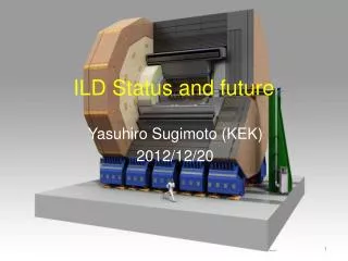
ILD Muon system/yoke Solenoid coil HCAL ECAL TPC LumiCAL BeamCAL FCAL LHCAL FTD SIT VTX
Vertex detector • Excellent impact parameter resolution better than 5⊕10/pbsin3/2q is required for efficient flavor tagging • 3 layers of double-sided ladders (6 pixel layers) • Effect on pair-background rejection is expected, but not demonstrated yet • Barrel only: |cosq|<0.97 for inner layer and |cosq|<0.9 for outer layer • Point resolution <3um for innermost layer • Material budget: 0.3%X0/ladder=0.15%X0/layer • Sensor options: CMOS, FPCCD, DEPFET
Vertex detector • CMOS option • Pixel size: 17x17(L1), 17x85(L2), 34x34(L3-6) • Frame readout time: 10us~100us • Power consumption: 600W 10W by power pulsing • FPCCD option • Pixel size: 5x5 (L1-2), 10x10(L3-6) • Readout between trains • Power consumption: ~40W (no power pulsing) • DEPFET option • Experience at Belle-II • Frame readout time: 50us~100us • 5-single layer of all-Si ladder option • Cooling • CO2 cooling for FPCCD • Additional material budget is small: 0.3%X0 in end-plate 0.1%X0 in cryostat • Air cooling for CMOS/DEPFET FPCCD real size (12x62.4mm2) prototype DEPFET all Si ladder
Silicon tracking system • Silicon tracking system • SIT (Silicon Inner Tracker) • SET (Silicon External Tracker) • ETD (Endcap Tracking Detector) • FTD (Forward Tracking Detector) • Role of Silicon tracking system • Additional precise space points • Improvement of forward coverage • Alignment of overall tracking system • Time stamping • SIT/SET/ETD • Two/one/one false double-sided layers of Si strip • Material budget: 0.65%X0/layer • Same silicon strip tiles of 10cmx10cm with 50um pitch, 200um thick, edgeless sensors will be used • Point resolution of ~7um
Silicon tracking system • FTD • Two pixel discs and five false double-sided strip disks • Pixel sensor options: CMOS, FPCCD, DEPFET • Power consumption: 2kW/disk 100W/disk by power pulsing • Supercapacitor-based power distribution system • Low current from outside and high pulse current on the readout electronics board • Radiation hardness and lifetime to be studied
TPC • Time Projection Chamber: The central tracker of ILD • Tracks can be measured with many (~200/track) 3-dimensional r-f-z space points • srf<100um is expected • dE/dx information for particle identification • Two main options for gas amplification: GEM or Micromegas • Readout pad size ~ 1x6mm2 106 pads/side • Pixel readout R&D as a future alternative • Material budget: 5%X0 in barrel region and <25%X0 in endplate region • Cooling by 2-phase CO2
ECAL • Sampling calorimeter of tungsten absorber / Si or scintillator-strip sensitive layer sandwich • 30 layers / 24X0 • Si sensor: 5x5mm2 pixel size • Scintillator strip: 5x45mm2, read out by MPPC • Leak-less water cooling Other methods are also investigated
ECAL • Detector optimization • Si sensor is one of the cost drivers of ILD • How to reduce the cost • Reduce inner radius ? • Reduce number of layers ? • Si-Scintillator hybrid Performance is not degraded up to 50% 250 GeV jet Number of layers is different from the default configuration
HCAL • Sampling calorimeter with steel absorber (48 layers, 6lI) • Two options for the active layer • Scintillator tiles with analog readout AHCAL • Glass RPC with semi digital (2-bits) readout SDHCAL • Different mechanical structure is proposed by the two groups AHCAL module SDHCAL module
AHCAL • 3x3cm2 segmentation of 3mm thick scintillator read out by SiPM through wavelength shifting fiber (Elimination of WLS under study) • Software compensation (e/p ~1.2) technique was shown to work well through beam tests: 58%/E1/2 45%/E1/2 • Test beam results are also used for evaluation of GEANT4 physics list
SDHCAL • Active layer: GRPC with 1.2mm gap with 1x1cm2 signal pick-up pads • Demonstrated to work with power-pulsing in 3T B-field • Test beam at CERN PS and SPS • Still better resolution is expected using more detailed analyses
Forward calorimeters • LumiCal • Precise (<10-3) luminosity measurement • BeamCal • Better hermeticity • Bunch-by-bunch luminosity and other beam parameter measurements (~10%) • LHCAL • Better hermeticity for hadrons
Muon system • Active layers (14 for barrel, 12 for endcap) interleaved with iron slabs of return yoke • Baseline design adopts scintillator strips + WLS fiber + SiPM readout as the active layer • RPC is considered as an alternative • Used for muon identification and as a tail catcher of the HCAL
Coil and yoke • B field: Nominal 3.5T, maximum 4T • Anti-DID in the same cryostat • Self shielding in terms of radiation protection • Leakage field < 50G at 15m from IP • Magnet design • Similar to CMS: 3 barrel rings + 2 endcaps • Cryostat size: f=8.8m, L=7.8m • Coil is divided into 3 modules in z • Cold mass = 168t • Total weight = 13400t • Stored energy ~2.3GJ • Yoke design • Each barrel ring consists of 12 trapezoidal blocks of ~190t: 2300t for a ring • Endcap yoke consists of 12 sectors: total weight~3250t/side
Detector integration • Yoke and magnet • Solenoid cryostat, which supports all of the central detectors, is supported from central barrel yoke ring • Maximum deformation of the cryostat <2.5mm • Barrel HCAL (~600t) is supported by 2 rails inside the cryostat • Barrel ECAL modules are supported by rails attached to barrel HCAL • Endcap calorimeters are supported from the endcap yoke • TPC is supported from the cryostat • Inner trackers (SIT, FTD, VTX) are housed in a inner support structure (ISS), and the ISS is supported from TPC end-plate • Forward detectors (LumiCal, BeamCal, LHCA) are supported together with QD0 from a support tube extended from the external pillar
Detector integration • Detector assembly: site-dependent • Non-mountain site: CMS style • Pre-assembled and tested on surface • Large pieces (3 barrel rings + 2 endcaps) are lowered through vertical shaft • 3500t crane for the vertical shaft • Mountain site: Access through horizontal tunnel • Yoke rings are assembled underground • 250t crane(/detector) in the underground experimental hall • Detector service path • Detector services (cables and tubes) are considered seriously for ILD • Barrel detectors • services go through gap of central yoke rings • Endcap detectors • gap between endcap yoke and barrel yoke • Forward detectors • along the QD0 support structure
Calibration/alignment • Alignment procedure • Accurate positioning during construction of sub-detectors by coordinate measuring machine • Alignment at the installation phase by standard survey technique • Hardware alignment system during operation • Ultimate micro-meter order alignment by “track-based alignment” • Alignment techniques under R&D • IR laser alignment for Si strip detectors • Fiber Bragg Grating (FBG) sensors for mechanical structure alignment Smart support structure
Data acquisition • ILD DAQ: Trigger-less • Compared to LHC, ILD DAQ is less demanding in throughput, but the number of readout channels is >x10 larger Data suppression at detector level (digitization in front-end electronics) • Most of the data volume (99%) come from beam background • Design of the DAQ system is still at the conceptual design level
Software tools • Core tools • LCIO • Provides a hierarchical event data • Commonly used by ILD, SiD, CLIC • Gear: API for detector geometry • Mokka: GEANT4 based full simulation • Marlin: Framework for further processing of the simulated data • Detector models in Mokka • Realistic model: Mechanical support structures, electronics, cables, dead materials, and cracks are also implemented • Three models created • ILD_o1_v05: AHCAL and SiECAL • ILD_o2_v05: SDHCAL and SiECAL • ILD_o3_v05: AHCAL and ScECAL
Software tools • Marlin • Reconstruction and analysis system • Some new/updated packages have been developed for DBD analysis • Track reconstruction: Kaltest, IMarlinTrK, Clupatra, FwdTracking – replacing old Fortran code with C++ code • Particle flow: PandoraPFA • Secondary vertex tagging: LCFIVertex, LCFIPlus • Background overlay • Pair background is not overlaid in MC study • Two-photon background events are overlaid before reconstruction
MDI and experimental area • Push-pull • ILD (~14kt) is place on a platform (20x20x2.2m3) for push-pull operation • ILD has its own moving system (air pads and grease pads) on the platform • Alignment accuracy after movement should be <1mm • QD0 • QD0 is supported by a support tube which is supported from a pillar standing on the platform • Vibration of QD0 has to be less than 50nm above 1Hz
MDI and experimental area • Experimental area for flat surface • Z-shape experimental hall • f18m vertical shaft above IP • f10m vertical shaft in ILD garage (f8m for SiD) • Two f5m shafts for elevator/services • Experimental area for mountain site • I-shape experimental hall with garage alcoves for detector maintenance • Access through horizontal tunnel
ILD benchmark analysis is still on-going • All the numbers may change by the end of January 2013
Tracking performance • Detector coverage and material budget • More material budget than LOI because of more realistic detector implementation LOI
Tracking performance • Performance goal • s1/pT~2x10-5GeV-1 • srf=5⊕10/psin3/2q[um] Pt resolution for muon tracks Tracking efficiency for t tevents Impact parameter resolution
PFA performance • Performance goal • Jet energy resolution < 3.5% for efficient separation of W, Z, and Higgs in hadronic mode • sE/E = a/sqrt(E) is not applicable because particle density depends on Ejet • Jet energy resolution is slightly better than LOI due to improvement of reconstruction software Zu,d,s events |cosq|<0.7
Flavor-tag performance • New software LCFIPlus is used • Improvement from LOI can be seen although VTX point resolution is worsein DBD LOI
LOI benchmark * http://arxiv.org/abs/arXiv:1207.0300 H.Ono, AkiyaMiaymoto
1TeV benchmark • Jet clustering algorithm • kt algorithm is used for jet clustering to reject low pt and small q particles from gg background pile-up WWlnqq
1TeV benchmark • e+e- nnh • Higgs production cross section is larger than 250 GeV • Luminosity is larger than 250 GeV • Higgs mm channel can be measured Preliminary
1TeV benchmark • e+ e- W+ W- • Precise measurement of beam polarization • Two methods • Modified Blondel scheme: (+,+),(+,-),(-,+),(-.-) data required • Angular distribution of W Analysis not finished yet Blondel method
1TeV benchmark • e+ e- t t h • Fully hadronic mode (8 jets, no isolated lepton) and semi-leptonic mode (6 jets + 1 isolated lepton) were used • Main background: ttbb, ttZ, and tt • Multivariable analysis technique is effective to reduce the background • Preliminary result on accuracy of top Yukawa coupling with 500fb-1 (+0.8,-0.2) and 500fb-1 (-0.8,+0.2) • 7.0% for semi-leptonic mode • 6.5% for hadronic mode • 4.8% for combined data
LOI-DBD common benchmark • We used e+e- t t channel for the comparison between LOI and DBD analysis @500 GeV • Forward-backward asymmetry is determinedby hadronic decay mode • Vertex charge determination is needed good benchmark for vertex detector/finding • Results with 500fb-1, P(e-, e+)=(-0.8, +0.3) : • AtFB = (DBD) • AtFB = 0.334±0.0079 (LOI) Coming soon
Other physics processes • Higgs self coupling • Zhh final state at 500 GeV • 27% accuracy in Zhh cross section = 44% accuracy in l with 2ab-1 • nnhh final state at 1TeV • 17% accuracy in l with 2ab-1 (Fast simulation) • Full simulation study on going • Further t t study • AtFB by semi-leptonic decay mode • 1% measurement can be done • Athel (helicity asymmetry) measurement • t t at threshold: measurement of mtand as
Cost • Progress since LOI • Development of technological prototypes close to final design Information on costs • Integration of whole detector has been studied • New agreement on methodology and unit costsof cost drivers • ILD current cost evaluation • Study is on-going • ~500 MILCU including manpower
Summary • Detailed baseline design of ILD based on validated detector technologies has been presented • Compared with LOI, more realistic design including support structure, cables, other services, and dead material has been made • Although the material budget has been increased, better detector performance than LOI has been obtained thanks to the improvement of software tools and analysis methods • New benchmark processes at 1 TeV have been studied with 2-photon process background overlaid (We still need few weeks to finalize the results, though) • We still need detector R&D, particularly in the engineering aspect, after completion of DBD