Cortex-M3 Instruction Sets
Cortex-M3 Instruction Sets. Chapter 4 in the reference book. 8.5 Instruction Sets 8.5.1 Assembly Basics 8.5.1.1 Assembler Language: Basic Syntax In assembler code, the following instruction formatting is commonly used : label: opcode operand1, operand2,... ; Comments

Cortex-M3 Instruction Sets
E N D
Presentation Transcript
8.5 Instruction Sets 8.5.1 Assembly Basics 8.5.1.1 Assembler Language: Basic Syntax In assembler code, the following instruction formatting is commonly used : label: opcode operand1, operand2,... ; Comments • The label is optional, used to determine the address of the instruction. • The opcode is the instruction. • The number of operands in an instruction depends on the type of instruction. • Normally, the first operand is the destination of the operation • The text after each semicolon (;) is a comment. Note:the assembler syntax depends on which assembler tool you are using. Here we introduce the ARM assembler syntax.
Example: MOV R0, #0x12 ; Set R0 = 0x12 (hexadecimal) MOV R1, #‘A’ ; Set R1 = ASCII character A Immediate data are usually in the form #number • Define constants using EQU: NVIC_IRQ_SETEN0 EQU 0xE000E100 NVIC_IRQ0_ENABLE EQU 0x1 ... LDR R0, =NVIC_IRQ_SETEN0 ; LDR here is a pseudo instruction that ; convert to a PC relative load by ; assembler. MOV R1, #NVIC_IRQ0_ENABLE ; Move immediate data to register STR R1, [R0] ; Enable IRQ 0 by writing R1 to address ; in R0
Use DCB and DCD to define byte-size and word-size variables: Example: LDR R3, =MY_NUMBER ; Get the memory address value of MY_NUMBER LDR R4, [R3] ; Get the value code 0x12345678 in R4 ... LDR R0,=HELLO_TXT ; Get the starting memory address of HELLO_TXT BL PrintText ; Call a function called PrintText to display string ... MY_NUMBER DCD 0x12345678 HELLO_TXT DCB “Hello\n”,0 ; null terminated string
8.5.1.2 Assembler Language: Unified Assembler Language • UAL was developed to • allow selection of 16-bit and 32-bit instructions • make it easier to port applications between ARM code and Thumb code • The traditional Thumb syntax can still be used Example: ADD R0, R1 ; R0 = R0 + R1, using Traditional Thumb syntax ADD R0, R0, R1 ; Equivalent instruction using UAL syntax Note: with traditional Thumb instruction syntax, some instructions automatically change the flags in APSR; however, when the UAL syntax is used, whether the instruction changes the flag depends on the Ssuffix, e.g., ADDS R0, R0, R1
With UAL, you can explicitly specify whether a Thumb or a Thumb-2 instruction you want by adding suffixes Example: ADDS R0, #1 ; Use 16-bit Thumb instruction by default for smaller size ADDS.N R0, #1 ; Use 16-bit Thumb instruction (N=Narrow) ADDS.W R0, #1 ; Use 32-bit Thumb-2 instruction (W=wide) Note: In most cases, applications will be coded in C, and the C compilers will use 16-bit instructions if possible due to smaller code size
32-bit Thumb-2 instructions can be half word aligned Example: 0x1000 : LDR r0,[r1] ; a 16-bit instructions (occupy 0x1000-0x1001) 0x1002 : RBIT.W r0 ; a 32-bit Thumb-2 instruction (occupy 0x1002- ; 0x1005) • Most of the 16-bit instructions can only access registers R0 to R7 • 32-bit Thumb-2 instructions do not have this limitation
8.5.2 Instruction List 16-Bit Data Processing Instructions
32-Bit Branch Instructions Other 32-Bit Instructions
8.5.3 Instruction Descriptions 8.5.3.1 Assembler Language: Moving Data Data transfers can be of one of the following types: 1. Moving data between register and register 2. Moving data between memory and register 3. Moving data between special register and register 4. Moving an immediate data value into a register
MOV: move data between registers or immediate data to register • e.g., MOV R8, R3; R3->R8 • MVN (move negative) • Load and Store: Load transfers data from memory to registers, and Store transfers data from registers to memory
Multiple Load and Store: LDM (Load Multiple); STM (Store Multiple).
“!” in the instruction MOV specifies whether the register Rd should be updated after the instruction is completed Example: STMIA.W R8!, {R0-R3} ; if R8 equals 0x8000, R8 changed to ; 0x8010 after store (increment by 4 words) STMIA.W R8 , {R0-R3} ; R8 unchanged after store Pre-indexing and Post-indexing: Example: LDR.W R0,[R1, #offset]! ; Read memory[R1+offset], with R1 ; update to R1+offset LDR.W R0,[R1], #offset ; Read memory[R1], with R1 ; updated to R1+offset
Usually a PUSH instruction will have a corresponding POP with the same register list, but this is not always necessary PUSH {R0-R3, LR} ; Save register contents at beginning of subroutine .... ; Processing POP {R0-R3, PC} ; restore registers and return • Use the instructions MRS and MSR to access special registers MRS R0, PSR ; Read Processor status word into R0 MSR CONTROL, R1 ; Write value of R1 into control register Note: APSR can be accessed using normal instructions
Where are immediate data? • Moving immediate data into a register: MOV R0, #0x12 ; Set R0 to 0x12, for data below 8 bits MOVW.W R0,#0x789A ; Set R0 to 0x789A, for data over 8 bits but ; below 16 bits, using Thumb-2 instruction MOVW.W R0,#0x789A ; Set R0 lower half to 0x789A MOVT.W R0,#0x3456 ; Set R0 upper half to 0x3456. Now ; R0=0x3456789A • LDR (LDR pseudo-instruction, not the LDR instruction): • A pseudo instruction provided in ARM assembler (not a real instruction) to load a register with either a 32-bit constant or an address LDR R0, =0x3456789A ; load an 32-bit constant LDR R0, =label+offset ; load an address
For Cortex-M3, if the address (i.e., value of a label) is a program address value, it will automatically set the LSB to 1 to indicate that it is Thumb code LDR R0, =address1 ; R0 set to 0x4001 ... address1 0x4000: MOV R0, R1 ; address1 contains program code ... • If the address is a data address, LSB will not be changed. LDR R0, =address1 ; R0 set to 0x4000 ... address1 0x4000: DCD 0x0 ; address1 contains data ...
8.5.3.2 Assembler Language: Processing Data • Many data operation instructions can have multiple instruction formats. Example: ADD ADD R0, R1 ; R0 = R0 + R1 ADD R0, #0x12 ; R0 = R0 + 0x12 ADD.W R0, R1, R2 ; R0 = R1 + R2 • When 16-bit Thumb code is used, an ADD instruction automatically changes the flags in the PSR. • 32-bit Thumb-2 code can either change a flag or keep it unchanged ADD.W R0, R1, R2 ; Flag unchanged ADDS.W R0, R1, R2 ; Flag change
Examples of Arithmetic Instructions Refer to the reference book for other logical operation instructions and rotate and shift instructions. Then answer the question: why are there only rotate right operations but no rotate left operations?
8.5.3.3 Assembler Language: Call and Unconditional Branch • The most basic branch instructions are: B label ; Branch to a labeled address BX reg ; Branch to an address specified by a register Note: In BX instructions, the LSB of the value contained in the register determines the next state (Thumb/ARM) of the processor. In Cortex-M3, since it is always in Thumb state, this bit should be set to 1; otherwise, the program will cause a usage fault exception. • To call a function: BL label ; Branch to a labeled address and save return address in LR BLX reg ; Branch to an address specified by a register and ; save return address in LR.
Branch using MOV, LDR and POP instructions MOV R15, R0 ; Branch to an address inside R0 LDR R15, [R0] ; Branch to an address in memory location specified by R0 POP {R15} ; Do a stack pop operation, and change the program ; counter value to the result value. Note: 1) also need to make sure that the LSB of the new program counter value is 0x1 (indicating the state of the next instruction is Thumb state) 2) BL instruction will destroy the content of LR. If you need the LR later, you should save the LR before using BL. For example, PUSH {LR}
8.5.3.4 Assembler Language: Decisions and Conditional Branches • In the APSR, there are five flag bits; four of them are used for branch decisions. Flag bits in APSR That Can Be Used for Conditional Branches
With combinations of the four flags (N, Z, C, and V), 15 branch conditions are defined. Conditions for Branches or Other Conditional Operations
(Continued) Example: BEQ label ; Branch to address ‘label’ if Z flag is set Thumb-2 version BEQ.W label ; Branch to address ‘label’ if Z flag is set
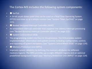
8.5.4 Several Useful Instructions in the Cortex-M3 8.5.4.1 MRS and MSR • Provide access to the special registers. MRS <Rn>, <SReg> ; Move from Special Register MSR <SReg>, <Rn> ; Write to Special Register Special Register Names for MRS and MSR Instructions
(Continued) Example: LDR R0, =0x20008000 ; new value for Process Stack Pointer (PSP) MSR PSP, R0 Note: Unless accessing the APSR, the MRS and MSR instructions can be used in privileged mode only.