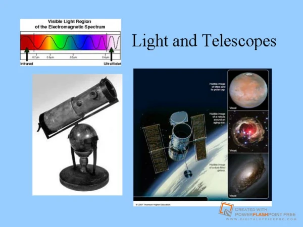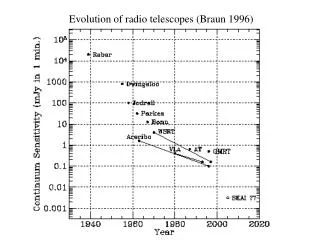
Evolution of Radio Telescopes: From Karl Jansky to Modern Innovations
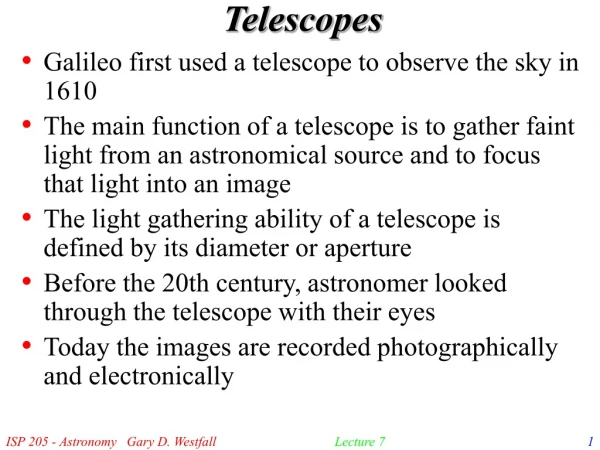
This overview traces the development of radio telescopes, starting from Karl Jansky's pioneering antenna in 1931, which detected cosmic radio emissions from Sagittarius. Highlighting Grote Reber’s 32-foot dish telescope in 1937, we explore key advancements in radio astronomy, including the innovative use of radio frequency sensors, cooling techniques for reduced noise, and advances in signal amplification. Understanding the radio spectrum and the importance of precision in telescope dish construction further enriches our appreciation of radio astronomy’s role in exploring the cosmos.

Evolution of Radio Telescopes: From Karl Jansky to Modern Innovations
E N D
Presentation Transcript
Karl Jansky built a radio antenna in 1931. Polarized array Study lightning noise Detected noise that shifted 4 minutes each day. Direction of Sagitarrius Consistent with galactic source Jansky’s Telescope
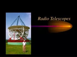
In 1937, Grote Reber built a 32-foot-diameter parabolic dish antenna in his backyard in Wheaton, Illinois to seek cosmic radio emissions. Reber Telescope
Reber’s Map In the spring of 1939, he was able to detect cosmic radio emissions with his equipment. In 1941, he made the first survey of the sky at radio wavelengths (160MHz).
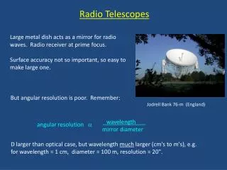
The radio spectrum is divided into three bands. Radio Spectrum
Atmospheric Window • The atmosphere is transparent from 50 m to 0.5 mm • Long wavelengths reflected by ionosphere • Short wavelength absorbed by O2, H2O; less at altitude
Radio sources are measured in Janskys (Jy). 1 Jy = 10-26 W m-2 Hz-1 Differential flux Fn Thermal emission follows the Rayleigh – Jeans law. Synchrotron radiation comes from magnetic fields. Radio Emission
For MHz radio waves a telescope is a half-wave dipole antenna. Consists of two conductors Short separation Quarter wavelength each Cables at the center connect to the receiver. Antenna Jocelyn Bell and 81.5 MHz radio telescope (1967)
Horn antennas are used to collect waves at GHz and higher. Factor of 8 in bandwidth May be dielectric filled Waveguides to detector Radio Horns ~1 meter ~2cm VLBA telescope
Radio sensors are matched to the desired wavelengths. High frequency sensors are usually SIS. Superconductor-insulator-superconductor NiO – AlO Photon assisted tunneling Sensors VLBA telescope
Small radio signals can be lost in noise. Minimum detectable brightness Bmin Integration time t Frequency bandwidth Dn Receiver-based constant K Noise temperature based on multiamplifier stages with gain Gn. Noise
One way to lower noise is to operate the electronics at low temperature. Reduces thermal noise Cooling to less than 20K is accomplished with high pressure helium gas. Compressor and pump Thermally isolated cryostat Cryogenics Helium pump Cryostat
Components Horn Purpose of the horn is to collect the radiation directed to it from the antenna. Amplifier Increases the amplitude of the signal Mixer Used to change the frequency to a more easily used frequency
The simplest receiver is a heterodyne receiver similar to a consumer radio. Preamp gain 10-1000 A local oscillator mixes with the input signal. Beat or intermediate frequency Further amplification may be by factors of 106 to 109. Heterodyne receivers have high system temperatures. 10 K at radio 10 M at millimeter Phase sensitive techniques reduce noise. Heterodyne
Receivers Horn Radio Preamp Mixer Convert to desired form to record/analyze Store data Millimeter and Submillimeter Convert to desired form to record/analyze Store data
Radio Receiver Receivers are inside the dome Aricibo
Millimeter Wave Receiver Horns ~0.5 m Amplifiers
Millimeter Wave Oscillator Local oscillator
Millimeter Wave Electronics Intermediate frequency (IF) plate
Submillimeter receiver CSO, Mauna Kea
Submillimeter receiver CSO, Mauna Kea 230 GHz mixer block
A radio telescope is often noted for the large dish. This is for the same optics as an optical reflecting telescope. Rayleigh criterion applies Beam width at first nulls Dipole length x Antenna Dish Steering gear Receiver Antenna mirror
The maximum gain for a radio telescope depends on the effective area. Typically 1.6 for half-wave dipole The effective area compares the output power to the incoming flux. Must be correctly polarized Gain
The surface error of a dish must be controlled. Less than 1/20 wavelength Losses to less than 30% Surface Errors 1/20 l=0.15mm Radio VLBA (3mm-3m) Mauna Kea
Very Smooth • The surface error requirements are much stricter for sub-millimeter telescopes than for radio telescopes. 1/20 l=0.015mm Sub-millimeter 1/20 l=0.05mm Millimeter NRAO 12 meter (1mm-3mm) Kitt Peak JCMT (0.3mm-2.0mm) Mauna Kea
This image was taken during the SMT reflector's holographic testing showing that the deviations of the reflector. Deviations are nearing the targeted 15 microns (about the thickness of a human hair). Holographic Test