zhenning
Uploaded by
203 SLIDES
2039 VUES
2030LIKES

Solidworks tutorial

DESCRIPTION

Solidworks for beginners

1 / 203

Télécharger la présentation

Solidworks tutorial

An Image/Link below is provided (as is) to download presentation Download Policy: Content on the Website is provided to you AS IS for your information and personal use and may not be sold / licensed / shared on other websites without getting consent from its author. Content is provided to you AS IS for your information and personal use only. Download presentation by click this link. While downloading, if for some reason you are not able to download a presentation, the publisher may have deleted the file from their server. During download, if you can't get a presentation, the file might be deleted by the publisher.

E N D

Presentation Transcript


  1. Solidworks

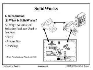
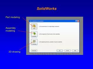
  2. Click New , Click Part and OK. How to create simple cube

  3. Click on Top Plane and click Sketch.

  4. Click Rectangle , sketch a rectangle start from origin.

  5. Click Smart Dimension , click side edge and click top edge to dimension it as 1.0in x 1.0in.

  6. Click Features>Extruded Boss/Base

  7. set D1 as 1.0in and click

  8. It’s done.

  9. How to create helical gear

  10. Click New , Click Part and OK.

  11. Click Front Plane and click on Sketch.

  12. Click Circle and sketch a circle center at origin. Click Smart Dimension, click sketched circle and set it diameter to 1.0in.

  13. Click Features>Extruded Boss/Base Set D1 to 0.3in

  14. And click

  15. Click on front face and click Normal To.

  16. Click on front face and click Sketch.

  17. Click on Centerline, and sketch vertical Centerline.

  18. Click Line and sketch gear teeth profile.

  19. Click Smart Dimension, dimension sketch as sketched below.

  20. Click Exit Sketch, change view to Isometric.

  21. Click scroll mouse button and rotate the part to back side.

  22. Click the back face and select Normal To. Click on this face again and click Sketch.

  23. We will trace last sketch to this face, while holding CTRL click all sketched line

  24. and click Convert Entities . Now we need removed all relation between this sketch and the other sketch, click Display/Delete Relations click Delete All and

  25. Click and drag select all the sketch line.

  26. Click on Rotate Entities,

  27. Click Center of Rotation box

  28. and click origin (center part).

  29. On Parameter option enter 10 deg rotation.

  30. Click Exit Sketch, change view to Isometric.

  31. Click Features>Lofted Boos/Base,

  32. open up part tree and double click Sketch2 and Sketch3 to add for lofted features.

  33. Make sure two green point is at the same edge as other sketch, if not drag and relocate it.

  34.   Click on Loft1 (gear teeth) and click Circular Pattern.

  35. Click on the cylinder face as axis of rotation (or click on View>Temporary Axes select the temporary axis as axis of rotation).

  36. Set Instances to 22

  37. Click on Front face and select Normal To.

  38. Click on front face and select Sketch.

  39. Sketch a Circle and sketch a circle center at origin. Click Smart Dimension, dimension sketch as 0.40in circle.

  40. Click Features>Extruded Cut and set Direction to Through All

  41. Click on front face and select Sketch.

  42. Click Rectangle and sketch a rectangle as sketched. Click Smart Dimension, dimension rectangle asskecthed below.

  43. Click Features>Extruded Cut and set Direction to Through All

  44. How to make part transparent

  45. Click on part body and select Appearances

  46. Select the top in the list…

  47. On left side, Appearance, set Transparency to 0.50 and OK.

More Related