Download

1 / 24
240 likes | 383 Vues
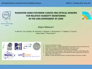
The Mu-ray Detector technology. The “Shadow” of the Vesuvius. 0.5 m. 32 scintillator strips. WLS optical fibers. Opto -electronic connector to photo-multipliers. The Basic Module Idea. Some Details on Preparation . Optical connector. Fibers. Scintillators. Arbitrary Unit.

E N D
0.5 m 32 scintillator strips WLS optical fibers Opto-electronic connector to photo-multipliers The Basic Module Idea
Some Details on Preparation Optical connector Fibers Scintillators Arbitrary Unit
Inside The Basic Module • Triangular shape reduce death spaces, gives more strength to the module and allow for charge balance method • Best optical gluing solution were adopted to avoid light losses due to intra-scintillator scattering or wrong coupling with photon detectors
The Basic Module • The Basic Module is an ensemble of 32 plastic scintillators disposed side by side • Each scintillator has a WLS fiber glued inside • The 32 fibers are collected to the so called optical connector
Fibers couplings FIBERS TO OPTICAL CONNECTOR FIBERS TO SCINTILLATORS
Bare Telescope • The plane is assembled with 4 modules: 2 used for the X coordinate and 2 for the Y one • A telescope is constituted by 3 planes • With this system we are able to track the trajectory of real muons passing through the telescope and reject the events mimicking muons
Trace Muons Through Detection of Light When a muon passes through the MU-RAY detector, deposits a certain amount of energy, turned into blue light by scintillators. The WLS fibers entrap produced light and lead it to the optical connector where it will be revealed by Silicon PhotoMultipliers (SiPM). Due to the shape of the scintillators, in each station will be switched on two neighbors X SiPMs and two Y ones and if all the three “points” are aligned the trace correspond to the passage of a real muon fake m from ‘shower’ m fake m from ‘albedo’
Silicon Photomultiplier and SPIROC Sensors housing board SiPM SLAVE board
Photo-detection efficiency (10%-60%) Linearity ( if n photons << n cells) High gain (105-106) Single photon detection sensitivity Fast (≈ 1 ns rise time) Good time resolution (< 100 ps) Low bias voltages ( < 100 V) very low power consumption (10 mW) Insensitive to B field Extremely compact and robust Breakdown voltage and dark rate depend on temperature Silicon Photomultiplier in Detail SIGNAL CAPTURED BY FAST SCOPE (AVERAGE MODE) WITHOUT INTERMEDIATE ELECTRONICS LeCroy SDA 760Zi: 6 GHz
Bi-gain low noise preamp Low noise charge preamplifier capacitivelycoupled = voltage preamplifier Gain adjustable with 4 bits common to all preamps : Cf=0.1, 0.2, 0.4, 0.8 pF Positive input pulse 8 mV/pe in High Gain Noise : 1.4 nV/sqrt(Hz) Power : 2 mW (unpulsed) Low gain at preamp level 0.8 mV/pe, MAX : 2000 pe (300pC) EASIROC features 0.1pF-1.5pF 1.5pF +HV 8-bit DAC Si PM ASIC
EASIROC main Functions 1.32 CH LOW GAIN, PROGRAMMABLE SHAPING, VOLTAGE MEASUREMENT PATH THAT HAS SAMPLE AND HOLD CAPABILITY 2.32 CH HIGH GAIN , PROGRAMMABLE SHAPING, LIKE PREVIOUS ONE 3.32 CH FAST TIMING PATH, WITH COMMON THRESHOLD PROGRAMMABLE COMPARATOR WITH 32 OUTPUTS. MAIN DATA IN TIMING APPLICATION AND ARE FED TO THE FPGA CHIP TO BE PROCESSED AS REQUESTED. SiPM BIAS VOLTAGE CAN BE PRECISELY ADJUSTED FOR EACH CHANNEL BY A PROGRAMMABLE 5V DAC «OR32» FAST SIGNAL USED TO TRIGGER ACQUISITION SEQUENCE IN ORDER TO PROPERLY CONFIGURE AND PROGRAMM THE CHIP, 3 REGISTERS CAN BE SERIALLY ACCESSED : «SLOW CONTROL» REG, »READ» REG. , «PROBE» REG.
EASIROC with single SiPM DISCRETE ANALOG CIRCUIT TO MANUALY ADJUST HOLD TIMING FOR EASIROC CHIP MICROCOAX 100 OHM DIFFERENTIAL CONNECTION TO FE-SIPM-PCB SIPM TEST SET-UP using the modifiedhybrid • LABVIEW SIMPLE INTERFACE ALLOW TO PROGRAM EASI-ROC CHIP REGISTERS • SLOW CONTROL, • READ AND PROBE REGISTERS • - WE CAN ALSO SET OVER-BIAS FOR EACH SINGLE SIPM THROUGH A DAC SETTING EASIROC BASED DAQ BOARD PROGRAMMABLE PREAMPS GAIN USB PC COMMUNICATE THROUGH A USB INTERFACE MULTILAYER RIGID-FLEX PCB SUPPORT FOR SIPM DETECTOR WITH GOOD SHIELDING PROPERTIES TRIGGER OUT PROBING AREA EXTERNAL AUXILIARY CIRCUIT TO EASILY TEST AND DEBUG TAB SELECT DIFFERENT REGISTERS COAX CONNECTOR FOR ANALOG SIGNAL PROBING (BUFFERED) FBK-IRST SIPM BONDED ON PCB. PLACE AVAILABLE ALSO FOR OTHER DETECTORs (HAMAMATSU) PRELIMINARY MEASURMENTS MADE WITH A FAST SCOPE
Hamamatzu FBK HM TJ2313 Vb=(73.5-1.5)V, I=1.3uA, T=22.4oC Dark 60ns G=14, F2 - maximum. 1 photon peak EASIROC tests 4-6 mV / photon 7 mV / photon 2 photon peak MAX 220mV MAX 20-25 mV 20mV/Div 100mV/Div
Slave board’s Features • The analog signals produced by SiPMs are converted in digital data • Dynamic tuning of the working point • Onboard pins to read temperature and humidity sensors • Setup for best performances corresponding to environmental conditions Housing board’s Features • Hosts 32 SiPM and guarantee for best positioning respect to module’s fibers • It has an isothermal surface to setup the same temperature condition to all 32 photomultipliers • Temperature sensors are placed close to the SiPMs • Humidity sensors to not exceed the dew point
Temperature control system • Based on Peltier cells • Designed to minimize inetrnal temperature variations due to external changes • Sets temperature condition for all housed SiPMs at the same time • Works with passive cooling
Data Acquisition… SLAVE Boards PC … and Slow Control
RPi Micro System MASTER board Slow Control Power generators Thermometer Internet Hard Disk
Full Automation Environment Sensors Raw data Main Program (Python3) Low Level Functions (C/C++) Apply new settings Master Board / Power Supplies Data Base (MySQL)
Remarks • The construction of the MU-Ray detector starts in the spring of 2011 • Tests and experiments to find best materials, sensors, computing and monitoring solutions lead to the development of an automated muon detector • There have been many improvements during its assembly • Other improvements and new features are scheduled for the 2013/14 • Its precise calibration and characterization allowed to set for best performance • In April 2013 we “see” the Vesuvius, our hard playground, for the first time and after few days of data acquisition • Other improvements and new features are scheduled for the 2013/14 • Since June 2013, the detector is in Clermont Ferrand (France) at the Puy-de-Dome
The Puy de Dome’s “Shadow” MuRay - Tomuvol Experiments collaboration in Clermont-Ferrand (France)
Thanks mail :: cimmino@na.infn.it