Download
1 / 39
390 likes | 468 Vues
Understanding link layer services in computer networking, including encoding, framing, error detection, and more. Learn how data is transmitted efficiently and accurately at the link layer level.

E N D
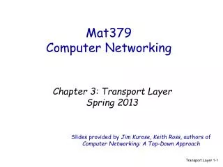
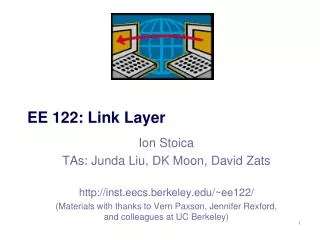
EE 122: Link Layer Ion Stoica TAs: Junda Liu, DK Moon, David Zats http://inst.eecs.berkeley.edu/~ee122/ (Materials with thanks to Vern Paxson, Jennifer Rexford,and colleagues at UC Berkeley)
Goals of Today’s Lecture • Link-layer services • Encoding, framing, error detection, transmission control • Error correction and flow control • Arbitrating access to a shared medium • Channel partitioning • Taking turns • Random access • Carrier sense • Collision detection
HTTPmessage TCP segment IP packet IP packet IPpacket IP IP IP Ethernet interface Ethernetframe SONET frame Ethernet frame Message, Segment, Packet, and Frame host host HTTP HTTP TCP TCP router router IP Ethernet interface SONET interface Ethernet interface Ethernet interface SONET interface
frame frame Adaptors Communicating datagram link layer protocol adapter receiving node adapter sending node • Link layer implemented in adaptor (network interface card; NIC) • Ethernet card, 802.11 card • Sending side: • Encapsulates datagram in a frame • Determines local addressing, adds error checking, controls transmission • Receiving side • Recognizes arrival, looks for errors, possibly acknowledges • Extracts datagram and passes to receiving node
Link-Layer Services • Encoding • Representing the 0s and 1s • Framing • Encapsulating packet into frame, adding header, trailer • Using MAC addresses rather than IP addresses • Error detection • Errors caused by signal attenuation, noise • Receiver detects presence, may ask for repeat (ARQ) • Resolving contention • Deciding who gets to transmit when multiple senders want to use a shared mediaFlowcontrol (pacing between sender & receiver)
Encoding • Signals propagate over physical links • How do we represent the bits? • Physical layer issue • Simplify some electrical engineering details • Assume two discrete signals, high and low • E.g., could correspond to two different voltages • Basic approach • High for a 1, low for a 0 • How hard can it be? • Sender & receiver agree: what’s “high”, what’s “low” • And: when to read the signal
NRZ (non-return to zero) Clock Receiver reads the signal on the clock’s leadingedge Sender begins to transmit signal on clock’s fallingedge Non-Return to Zero (NRZ) • 1 high signal; 0 low signal • (Actual signals are of course not so sharp) • How does receiver know where one bit stops and another begins? 0 0 1 0 1 0 1 1 0
Clock Coordination • How do the sender and receiver agree on the running of the clock? • Problem: without explicit synchronization, receiver’s clock can drift with respect to sender’s 0 0 1 0 1 0 1 1 0 NRZ Clock
Here we slip a bit, reading a 0 on leading edge rather than the correct 1 Clock Drift 0 0 1 0 1 0 1 1 0 NRZ Sender’s Clock Clock Receiver’s Clock … … can drift
Clock Recovery • To avoid clock drift, we use the signal itself to coordinate • Whenever see a transition (0 1 or 1 0) we know that corresponds to sender clock’s trailing edge • So pull our clock in phase towards it • Problem with NRZ: long strings of 0s or 1s • Quite common • No transitions from low-to-high, or high-to-low • Clock recovery fails and receiver’s clock begins to drift
NRZI (non-return to zero inverted) 0 0 1 0 1 0 1 1 0 Clock (read onfalling edge) Non-Return to Zero Inverted (NRZI) • 1 make transition; 0 stay at same level • Fixes previous problem for long sequences of 1’s • But not for 0’s
0 0 1 0 1 0 1 1 0 Manchester Clock (read on eachrising edge) Manchester Encoding • 1 high-to-low transition; 0 low-to-high transition • Addresses clock recovery problems • But: physical signaling must be twice as fast • To support 2 transitions/cycle Efficiency of 50%
4-bit 5-bit 4-bit 5-bit • 1000 10010 • 1001 10011 • 1010 10110 • 1011 10111 • 1100 11010 • 1101 11011 • 1110 11100 • 1111 11101 • 0000 11110 • 0001 01001 • 0010 10100 • 0011 10101 • 0100 01010 • 0101 01011 • 0110 01110 • 0111 01111 4-bit/5-bit (100Mb/s Ethernet) • Goal: address inefficiency of Manchester encoding, while avoiding long periods of no transition • Solution: • Use 5 bits to encode every sequence of four bits such that • No 5 bit code has more than one leading 0 or two trailing 0’s • Use NRZI to then encode the 5 bit codes • Efficiency is 80%
5 Minute Break Questions Before We Proceed?
Framing • Specify how blocks of data are transmitted between two nodes connected on the same physical media • Service provided by the data link layer • Implemented by the network adaptor • Challenges • Decide when a frame starts & ends • How hard can that be?
21 Frame content 53 58 Frame content Frame content 21 bytes of data 53 bytes of data 21 Frame content 94 Bogus new frame length; desynchronization 58 bytes of data misdelivered Simple Approach to Framing: Counting • Sender: begin frame with byte(s) giving length • Receiver: extract this length and count • How can this go wrong? • On occasion, the count gets corrupted
01111110 Frame content 01111110 Framing: Sentinels • Delineate frame with special pattern • Both can be the same, e.g., 01111110 • Problem: what if sentinel occurs within frame? • Solution: escape the special characters • Sender: insert a 0 after five 1s in data portion • Receiver: when it sees five 1s makes a decision on next two bits: • If next bit 0 (this is a stuffed bit), remove it • If next bit, look at next bit • If 0, this is end of frame (receiver has seen 0111110) • If 1 this is an error, discard frame (receiver as seen 01111111)
Example 01111110 0111111011111011111001 01111110 Sender: stuff bits Five 1s insert a 0 • 01111110 0111110101111100111110001 01111110 Receiver: identify & remove stuffed bits Five 1s and next bit 0 remove it Five 1s, and next two bits 10 end/start frame 01111110 0111111011111011111001 01111110
Clock-Based Framing (SONET) • SONET (Synchronous Optical NETwork) • SONET endpoints maintain clock synchronization • Frames have fixed size (e.g., 125 sec) • No ambiguity about start & stop of frame • But may be wasteful • NRZ encoding • To avoid long sequences of 0’s or 1’s payload is XOR-ed with special 127-bit pattern w/ many 0-1/1-0 transitions • What problem can that lead to?
Error Detection • Errors are unavoidable • Electrical interference, thermal noise, etc. • Error detection • Transmit extra (redundant) information • Use redundant information to detect errors • Extreme case: send two copies of the data • Trade-off: accuracy vs. overhead • Techniques for detecting errors • Parity checking • Checksum • Cyclic Redundancy Check (CRC)
Error Detection: Parity • Add an extra bit to a 7-bit code • Odd parity: ensure an odd number of 1s • E.g., 0101011 becomes 01010111 • Even parity: ensure an even number of 1s • E.g., 0101011 becomes 01010110 • Overhead: 1/7th • Power: • Detects all 1-bit errors • But: can’t detect an even number of bit errors in a word • Can use more bits to gain more power
Error Detection Techniques, con’t • Internet Checksum • Treat data as a sequence of 16-bit words • Compute ones-complement sum of all the 16-bit words • Intermingles integrity of a large group of data • Overhead: 16 bits • Power: • Catches 1-bit errors, most other errors • But not, for example, same bit flipped in two different words • Cyclic Redundancy Check (CRC) • Family of quite powerful, principled algorithms • Detects wide range of bit corruption patterns seen in practice • Used by most modern link layers • See K&R Section 5.2.3
Point-to-Point vs. Broadcast Media • Point-to-point: dedicatedpairwise communication • Long-distance fiber link • Point-to-point link between Ethernet switch and host • Broadcast: shared wire or medium • Traditional Ethernet • 802.11 wireless LAN
Multiple Access Algorithm • Single shared broadcast channel • Avoid having multiple nodes speaking at once • Otherwise, collisions lead to garbled data • Multiple access mechanism • Distributed algorithm for sharing the channel • Algorithm determines which node can transmit • Classes of techniques • Channel partitioning: divide channel into pieces • Taking turns: scheme for trading off who gets to transmit • Random access: allow collisions, and then recover • Optimizes for the common caseof only one sender
Rounds 0 1 2 4 5 0 1 2 4 5 3 3 Slots = Channel Partitioning: TDMA TDMA: Time Division Multiple Access • Access to channel in "rounds" • Each station gets fixed length slot in each round • Time-slot length is packet transmission time • Unused slots go idle • Example: 6-station LAN with slots 0, 3, and 4
time frequency bands FDM cable Channel Partitioning: FDMA FDMA: Frequency Division Multiple Access • Channel spectrum divided into frequency bands • Each station assigned fixed frequency band • Unused transmission time in frequency bands go idle • Example: 6-station LAN, 1,3,4 have pkt, frequency bands 2,5,6 idle
master data data poll slaves “Taking Turns” MAC protocols • Token passing • Control tokenpassed from one node to next sequentially • Node must have token to send • Concerns: • Token overhead • Latency • Single point of failure (token) Polling • Master node “invites” slave nodes to transmit in turn • Concerns: • Polling overhead • Latency • Single point of failure (master)
Random Access Protocols • When node has packet to send • Transmit at full channel data rate • No a priori coordination among nodes • Two or more transmitting nodes collision • Data lost • Random access MAC protocol specifies: • How to detect collisions • How to recover from collisions • Examples • ALOHA and Slotted ALOHA • CSMA, CSMA/CD, CSMA/CA
Key Ideas of Random Access • Carrier sense • Listen before speaking, and don’t interrupt • Checking if someone else is already sending data • … and waiting till the other node is done • Collision detection • If someone else starts talking at the same time, stop • Realizing when two nodes are transmitting at once • …by detecting that the data on the wire is garbled • Randomness • Don’t start talking again right away • Waiting for a random time before trying again
Where it all Started:AlohaNet • Norm Abramson left Stanford in search of surfing • Set up first radio-based data communication system connecting the Hawaiian islands • Hub at Alohanet HQ (Univ. Hawaii, Oahu) • Other sites spread among the islands • Had two radio channels: • Random access: sites sent data on this channel • Broadcast: only used by hub to rebroadcast incoming data
Assumptions All frames same size Time divided into equal slots (time to transmit a frame) Nodes are synchronized Nodes begin to transmit frames only at start of slots No carrier sense If two or more nodes transmit, all nodes detect collision Operation When node obtains fresh frame, transmits in next slot No collision: node can send new frame in next slot Collision: node retransmits frame in each subsequent slot with probability p until success Slotted ALOHA
Pros Single active node can continuously transmit at full rate of channel Highly decentralized: only slots in nodes need to be in sync Simple Cons Collisions, wasting slots Idle slots Nodes may be able to detect collision in less than time to transmit packet Clock synchronization Slotted ALOHA
Efficiency of Slotted Aloha • What is the maximum fraction of successful transmissions? • Suppose N stations have packets to send • Each transmits in slot with probability p • Probability of successful transmission S is(very approximate analysis!): by a particular node i: Si = p (1-p)(N-1) by exactly one of N nodesS = Prob (only one transmits) = N p (1-p)(N-1) <= 1/e = 0.37 but must have p proportional to 1/N
CSMA (Carrier Sense Multiple Access) • Collisions hurt the efficiency of ALOHA protocol • Utilization 1/e 37% • CSMA: listen before transmit • If channel sensed idle: transmit entire frame • If channel sensed busy, defer transmission • Human analogy: don’t interrupt others!
CSMA Collisions Collisions can still occur: propagation delay means two nodes may not hear each other’s transmission in time. At time t1, D still hasn’t heard B’s signal sent at the earlier time t0, so D goes ahead and transmits: failure of carrier sense. Collision: entire packet transmission time wasted
CSMA/CD (Collision Detection) • CSMA/CD: carrier sensing, deferral as in CSMA • Collisions detected within short time • Colliding transmissions aborted, reducing wastage • Collision detection • Easy in wired LANs: measure signal strengths, compare transmitted, received signals • Difficult in wireless LANs • Reception shut off while transmitting • Even if on, might not be able to hear the other sender, even though the receiver can • Leads to use of collision avoidance instead
CSMA/CD Collision Detection Both B and D can tell that collision occurred. This lets them (1) know that they need to resend the frame, and (2) recognize that there’s contention and adopt a strategy for dealing with it. Note: for this to work, we need restrictions on minimum frame size and maximum distance
Three Ways to Share the Media • Channel partitioning MAC protocols (TDMA, FDMA): • Share channel efficiently and fairly at high load • Inefficient at low load: delay in channel access, 1/N bandwidth allocated even if only 1 active node! • “Taking turns” protocols • Eliminates empty slots without causing collisions • Overhead in acquiring the token • Vulnerable to failures (e.g., failed node or lost token) • Random access MAC protocols • Efficient at low load: single node can fully utilize channel • High load: collision overhead
Next Lecture • Ethernet + bridges/hubs/switches • K&R 5.5, 5.6