TECHNICAL DATA
Introducing gigahertz-bandwidth photodetectors for the visible and near-IR spectral range that provide highest performance-to-price ratio available today!. We offer 2-GHz Si detectors for the visible and 6-GHz InGaAs detectors for the near-IR spectral range. TECHNICAL DATA. 0.6. 0.5. 0.4.

TECHNICAL DATA
E N D
Presentation Transcript
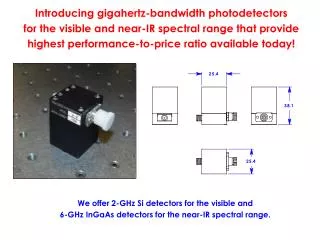
Introducing gigahertz-bandwidth photodetectors for the visible and near-IR spectral range that provide highest performance-to-price ratio available today! We offer 2-GHz Si detectors for the visible and 6-GHz InGaAs detectors for the near-IR spectral range.
0.6 0.5 0.4 Responsivity (A/W) 0.3 0.2 0.1 0 300 400 500 600 700 800 900 1000 1100 Wavelength (nm) Visible V-2 photodetector spectral and impulse response
10 1 0.1 Responsivity (A/W) 0.01 0.001 800 1000 1200 1400 1600 1800 Wavelength (nm) Near-IR IR-6 photodetector spectral and impulse response
Typical measurement setup Light pulse is coupled into a delivery fiber High-bandwidth adapter Delivery fiber Oscilloscope Photodetector
OPERATIONAL INSTRUCTIONS • Couple the light to be analyzed into a 50-m delivery fiber. Keep the energy and power of the coupled radiation below the damage threshold of the fiber tip/volume. • Attenuate the peak power of the optical pulse exiting the fiber to less than 100 mW. NOTE: if the photodetector input peak power is greater than 200 mW, the detector may be damaged and the warranty will not apply. • Connect the photodetector to an oscilloscope using a high-bandwidth SMA adapter. Using cables or low-bandwidth adapters will significantly degrade the quality of measurement. • Slowly insert the FC fiber connector into the photodetector fiber receptacle while watching the electrical signal on the oscilloscope. The maximum value of the signal must be lower than 2 V into 50 Ohm. Attenuate the input signal until the fiber connector can be completely inserted into receptacle without exceeding 2 V of output signal. • Upon completion of measurements disconnect the fiber from the photodetector or block the fiber input from the radiation to prevent unnecessary battery drain. • Always use protective plastic caps for the detector receptacles and fiber connectors.
20 V battery pack 1 2 3 Battery pack Electronic compartment #2-56 screws Electrical contacts – DO NOT TOUCH! Four #2-56 screws – SAVE THESE! • Changing the battery pack: • Unscrew four #2-56 screws (one at each corner) that hold the battery pack and the electronic compartment together. SAVE THESE SCREWS. • Remove the old battery pack and discard it. • Attach a new battery pack with four #2-56 screws. The battery pack has 90º rotational symmetry. Align it to the electronics compartment in any orientation.