The Unified Modeling Language
The Unified Modeling Language. Prof. Steven A. Demurjian † Computer Science & Engineering Department The University of Connecticut 371 Fairfield Road, Box U-2155 Storrs, CT 06269-2155. steve@engr.uconn.edu http://www.engr.uconn.edu/~steve (860) 486 - 4818.

The Unified Modeling Language
E N D
Presentation Transcript
The Unified Modeling Language Prof. Steven A. Demurjian† Computer Science & Engineering Department The University of Connecticut 371 Fairfield Road, Box U-2155 Storrs, CT 06269-2155 steve@engr.uconn.edu http://www.engr.uconn.edu/~steve (860) 486 - 4818 † Special Thanks to Prof. Heidi Ellis, Jack Reisner, and Oliver Scheck for providing portions of this material. Portions also excerpted from talks by three amigos (Booch, Rumbaugh, and Jacobson) on UML web page.
Overview of Lecture • The Role of Analysis and Design • Guidelines for Designing Components • History of OO Design • The Emergence of UML • Historical Perspective • Goals of UML • Modeling Capabilities • Software Process/Architectures • Concluding Remarks
The Role of Analysis and Design • Partitioning Software Construction • Requirements Analyses • Software Architecture • Specification (High-Level/Early Design) • Detailed Design • Implementation and Testing • Maintenance and Evolution • Each Design/Development Phase is Partitioned • Where Does OO Analysis and Design Fit?
The Role of Analysis and Design • Analysis • Investigating the Boundaries of a Problem • What are the Scope and Requirements? • How is the System Accessed? • Who needs Access to What When? • Determining WHAT needs to be Done! • OO Analysis • Identification of Critical Concepts in the Problem Domain that Correspond • Emphasis on Finding Objects and Components • What is Available to Facilitate OO Analysis?
The Role of Analysis and Design • Design • Development of a Logical Solution • Represents One Way to Solve Problem • Defining HOW System Fulfills WHAT! • OO Design • Emphasis on Defining Logical Software Objects and Components • Evaluate Alternative OO Designs • Leads to Implementation of a Feasible Solution • Warning: A+D are Processes on Continuum! • Successful and Verifiable A+D Can Lead to Quantifiable Software Engineering
Defining Component Concepts • A Component is Composed of One or More Classes (or Other Components) and is Intended to Support a “Constructed” Unit of Functionality • Classes Can be Utilized in Multiple Components • A Class Utilized in Multiple Components Maintains the “Same” Semantics in All of its Contexts • Our Interest Involves: • Component-Based Design • Interdependencies Among Components • Alternative Perspectives of Component Interactions • Framework for Reusable Components
Guidelines for Designing ComponentsSpecifying “Good” Components • Identifying a “Good” Component is Hard Work • A Well-Designed Component • Highly-Cohesive: • A Single Design Abstraction • May be Composition of other Abstractions • Promotes Loose Coupling: • Minimal Ties to Other Components • Encourage Interactions that Mirror “Real” World • Sufficient: • Captures “Enough” Characteristics for Efficient and Meaningful Operation • Represent “Real” World as it Occurs
Guidelines for Designing ComponentsSpecifying “Good” Components • A Well-Designed Component - Continued • Complete: • Characteristics Provide Wide Range of Useful Capabilities for Clients • Anticipate Current and Future Needs! • Non-Redundant: • No Two Components “Same” Functionality • Coordinate Team-Oriented Design Process • Predictable: • Behaves as Expected to Users • Users are Other Software Components, Applications, Tools, and “Real” End-Users
Guidelines for Designing ComponentsUnderstanding the Utility of Components • Three Categories of Software in Application • Domain-Independent (20%) • Applicable Regardless of Domain • Stack, List, etc. • Domain-Specific (65%) • Likely to be Used in Current and Future Projects • Inventory Control Components for Supermarkets, Auto Parts, Video Tape Rentals, etc. • Application-Specific (15%) • Cannot be Reused - Special Purpose • Components for a Particular or Specific Entity • Companies Must Strive for Domain-and-Organization Specific Reuse
Guidelines for Designing ClassesMaking Choices for Class Design • Containment versus Inheritance • Class A “Has-A” Class B • Class A has an Attribute of Type Class B • Instances of Class B Live Within Class A • Class A “Is-A-Kind-Of” Class B • Class A Needs to Acquire all Behavior of Class B • Class A is a Specialization of Class B • Specialization can Expand or Refine Behavior • Choose • Inheritance if Class B Used by Other Classes • Containment if Class B Dedicated to Class A • Overuse of Inheritance akin to Spaghetti Code!
Guidelines for Designing ComponentsMaking Choices for Component Design • Components and Containment • Component A Contains B, C, D, etc. • B, C, D - Classes and/or Components • Is Containment a Relationship? • Components and Inheritance • Can a Component Inherit from Another Component? • What are the Semantics of Such a Behavior? • Overuse of Containment akin to too Many Nested Procedures/Functions! • Overall: Designers Must Cooperate and Communicate!
History of OO Design • Over the Past 15+ Years, Many Players in OOD • Booch: The Booch Method • “Object-Oriented Design with Application,” Benjamin/Cummings, 1991. • Rumbaugh: OMT • “Object-Oriented Modeling and Design,” Prentice-Hall, 1991. • Meyer: Client/Server Contract Approach • “Object-Oriented Software Construction,” Prentice-Hall, 1988. • Jacobson: Use-Cases and Software Engrg. • “Object-Oriented Software Engineering: A Use Case Driven Approach,” Addison-Wesley, 1992.
History of OO Design • Players in OOD - continued • Coleman: The Fusion Method • “Object-Oriented Development - The Fusion Method,” Prentice-Hall, 1994. • Lieberherr: Adaptive OO Software • “Adaptive OO Software: The Demeter Method with Propagation Patterns,” PWS, 1996. • Gamma: Design Patterns • “Design Patterns: Elements of Reusable Object-Oriented Software,” Addison-Wesley, 1995. • Booch and Rumbaugh: UML Predecessor • “Unified Method for Object-Oriented Development,” Rational TR, 1995
The Emergence of UML • The Unified Modeling Language (UML) is the OOD&A Equivalent of Java • Unifies Booch, Rumbaugh, and Jacobson • Overview of UML Presentation • What is UML? • Seven Goals of UML • Modeling Constructs and Diagrams • Use-Case Diagrams • Class Diagram • Behavior Diagrams • Interaction Diagrams • Implementation Diagrams
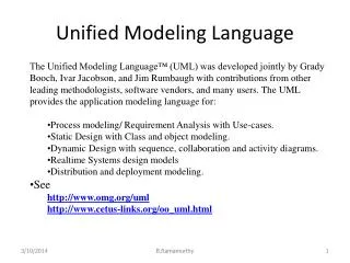
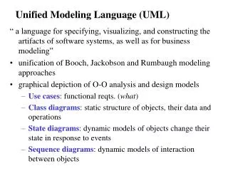
What is UML? • UML is a Language for Specifying, Visualizing, Constructing, and Documenting Software Artifacts • What Does a Modeling Language Provide? • Model Elements: Concepts and Semantics • Notation: Visual Rendering of Model Elements • Guidelines: Hints and Suggestions for Using Elements in Notation • References and Resources • Web: www.uml.org • “The Unified Modeling Language Reference Manual”, Addison-Wesley, 1999. • Addison-Wesley has an entire series on UML
A History of UML • Unification of Booch and Rumbaugh - 1994 • Version 0.8 Released in October 1995 • Ivar Jacobson and Objectory Joined Rational in Fall 1995 • UML 2.0 – Official version - In upgrading Phase • UML 1.5 – Previous Version - Complete • These “Three Amigos” Motivated by • Fact that Individual Methods Evolving Towards Each Other Independently • Unification of Semantics and Notation to Bring Stability to OO Design Marketplace • Anticipation that Unification would Improve Earlier, Individual Methods
Representing System Architecture End-user Functionality Logical View Implementation View Programmers Software management Use Case View Process View Deployment View System integrators Performance Scalability Throughput System engineering System topology Delivery, installation Communication Conceptual Physical
Creating the UML UML 2.0! UML 1.3 OMG Acceptance, Nov 1997 UML 1.1 Final submission to OMG, Sep ‘97 First submission to OMG, Jan ´97 UML 1.0 UML partners public feedback UML 0.9 Web - June ´96 Unified Method 0.8 OOPSLA ´95 UML 1.5 Booch method OMT OOSE Other Methods
Original UML Partners • Rational Software Corporation • Hewlett-Packard • I-Logix • IBM • ICON Computing • Intellicorp • MCI Systemhouse • Microsoft • ObjecTime • Oracle • Platinum Technology • Taskon • Texas Instruments/Sterling Software • Unisys
Contributions to the UML HP Fusion Meyer Booch Operation descriptions and message numbering Before and after conditions Booch method Rumbaugh Embley Harel OMT Singleton classes and high-level view Statecharts Gamma, et al Wirfs-Brock Frameworks and patterns, Responsibilities Odell Shlaer - Mellor Jacobson Classification Object lifecycles OOSE
Many Facets of Unification • Unification Context Across ... • Historical Methods and Notations • Standardization of Terminology • Common Notational Conventions • ASIDE: A Definite Plus Given History of OOD • Phases of Development Lifecycle • From Requirements Definition to Deployment • Utilization of Consistent Notation • Application Domains • Targeted for “Large, Complex, Real-Time, Distributed, Data, or Computation Intensive” • ASIDE: Is this Realistic?
Many Facets of Unification • Unification Context Across ... • Implementation Languages and Platforms • Intended for “Programming Languages, Databases, 4GLs, Organization Documents, Firmware, etc.” • ASIDE: Again, is this Realistic? • Development Processes • Intended for “Modeling Language Underlying Most Existing or New Development Processes” • ASIDE: Isn’t this OO Targeted? What if Next Generation is not OO/Components? • Internal Concepts • Self-Containment and Referential Nature of UML • Ability to Customize and Extend within UML
The Seven Goals of UML • Ready-to-Use, Expressive Visual Modeling Language that Promotes Development/Exchange • Extensibility/Specialization of Core Concepts • Independent of Programming Languages and Development Processes • Formal Basis for Understanding Language • Encourage Growth of OO Tools Market • Support Higher Level Design Concepts Collaborations, Frameworks, Patterns, etc. • Integrate the Best Practices of All OOD
The Nature and Purpose of ModelsWhat are Models For? • Precisely Capture Requirements and Domain Knowledge • Medium of Exchange/Agreement for Stakeholders • Manager, Designers, SEs, Maintainers, Builders, End Users, Customers, etc. • Multiple Representations of Requirements for Complementary Perspectives - Models for ... • External Behavior of System • Information Needs/Processing • Internal Classes and Components • For Example, DFDs, FSMs, ERs, etc.
The Nature and Purpose of ModelsWhat are Models For? • Classify and Understand Information • Organize, Find, Filter, Retrieve, Examine, and Edit Information • Modeling, Usage, Management Information • Explore Alternative Solutions • Construct and Evaluate Different Models • Determine “Best” Model Based on • Quantitative Analyses: Queueing, Simulation, Time-Complexity • Qualitative Examination of Features/Capabilities • Economically Feasible • Commercially Risky - Depends on Preciseness of Models and Confidence in Individuals
The Nature and Purpose of ModelsLevels of Models • High-Level at Earliest Stages • Target for Non-Technical Stakeholders • Conceptual Exploration of Problem • Refinement via Detailed Mid-Level Models • Mid-Level Models • Specification of Essential System Capabilities • Historically, ERs, DFDs, FSMs, etc. • Recently, Scenarios, Design Patterns, etc. • Detailed Models • Formal Models - For Example, IOA! • Security Models - URBS and DAC • What will be the Role of UML?
The Nature and Purpose of ModelsWhat Defines a Model? • Languages Defined by • Syntax: Constructs and Syntactical Context • Semantics: Meanings of Different Constructs • Pragmatics: Operational Semantics of System • In Programming Languages: • Syntax: Lexical Analysis and Parsing • Semantics: Attribute Grammars/Translation • Pragmatics: Dynamic Runtime Environment • How are Models Defined? • Semantics • Visual Presentation • Note: Can have Syntax and Pragmatics!
UML Modeling Constructs/DiagramsStatic vs. Dynamic Perspectives • A Diagram Is a View Into a Model • Presented From the Aspect of a Particular Stakeholder • Provides a Partial Representation of the System • Is Semantically Consistent With Other Views • In the UML, There Are Nine Standard Diagrams • Static Views: Use Case, Class, Object, Component, Deployment • Dynamic Views: Sequence, Collaboration, Statechart, Activity
UML Modeling Constructs/DiagramsClassification by Capability/Timeline • Use-Case Diagrams • Class and Object Diagrams • Behavior Diagrams • Statechart Diagrams • Activity Diagrams • Interaction Diagrams • Sequence Diagram • Collaboration Diagram • Implementation Diagrams • Component Diagram • Deployment Diagram
Relationship BetweenModels and Diagrams State Diagrams State Diagrams Class Diagrams Use Case Diagrams Use Case Diagrams State Diagrams Use Case Diagrams State Diagrams Use Case Diagrams Object Diagrams Use Case Diagrams Sequence Diagrams Scenario Diagrams State Diagrams Scenario Diagrams State Diagrams Component Diagrams Collaboration Diagrams Models Component Diagrams Scenario Diagrams Component Diagrams Scenario Diagrams Deployment Diagrams Statechart Diagrams Activity Diagrams
Static: Use-Case Diagrams (Jacobson) • Interaction of Users with System Components • Actors • External Entity that Interacts with Software • Promote Simulation of Events • Can be People, Classes, Software Tools, etc. • Use-Case Diagram • Graph of Actors and Set of Use Cases Enclosed by System (High-Level) or Class Boundary • Focus on What Actions, Methods, Functions, etc. are Utilized by Which Actors • Black Box View of System Components • Derived via User Interviews • Granularity Level of Use-Cases is Variable
Use-Case Diagrams Supermarket Example HTSS Scan Items Ring Order Customer Buy Items Catalog Cashier Check Status Place Order Sales Person Fill Order Customer Estb. Credit Supervisor HTSS: System View Catalog: Class View
Use-Case Relationships • Actors • Generalization from Child to Parent • Association to a Use Case • Use-Cases • Generalization • Child Use Case X to a Parent UC Y means that X inherits Behaviors/Meanings of Y • <<Include>> • Base UC C to Included UC D means that C contains the Behaviors defined in D • <<Extend>> • From Extending UC E to Base UC F means that F Augmented with Behaviors of E
Survey Management Example • A Survey Institution that performs/manages public surveys. After the raw survey data is collected, a senior staff adds a survey header into the database; senior or junior staff add questions into the survey, may categorize questions, or add a question category. Questions with sensitive content are restricted to senior staff.
Use Case ScenarioHealth Care Application (HCA) - Write Rx + • Physician Decides to Prescribe Medication for Patient • Physician Specifies Drug Info: Medication Name, Dosage Amount, Number Doses & Refills • Computer Cross-Checks for Conflict Between Medication and Current Medications/Medical History • Prescription Forwarded Electronically to Pharmacy or Else Printed for Patient
Use Case View • The Nouns in the Use Case: • Help Define System Classes and Class Attributes • The Verbs in the Use Case: • Help Determine Class Methods • The Prepositions in the Use Case: • Help Determine Relationships Between Classes • The Set of All System Use Cases: • Helps to Verify That System Design and Implementation • Does System Meet User Requirements? • Excellent Medium of Exchange between Users and Technical Personnel
Building a Conceptual Model • In UML, a Conceptual Model is the Set of Static Structure Diagrams with Classes, Attributes, and Associations, but no Operations • Analysis Goal: Build Conceptual Model • Represents an Aspect of Reality • Helps SEs Manage Complexity • Is Simpler than Reality • Conceptual Model Should: • Organize Data into Objects and Classes • Structure Data via Inheritance/Associations • Specify Behavior and Public Interfaces • Describe Global Behavior • Describe Constraints on System Behavior
Static: Class Diagram (Rumbaugh/Booch) • Utilized for Static Structure of Conceptual Model • Class Diagram Describes • Types of Objects in Application • Static Relationships Among Objects • Temporal Information Not Supported • Class Diagrams Contain • Classes: Objects, Attributes, and Operations • Packages: Groupings of Classes • Subsystems: Grouping of Classes/Packages • Main Concepts: Class, Association, Generalization, Dependency, Realization, Interface • Granularity Level of Use-Cases is Variable
Class Diagrams • A Class is a Description of Set of Objects that Share the Same Attributes, Operations, Methods, Relationships, and Semantics • Classes are Graphically Represented as Boxes with Compartments for • Class Name, Private Attributes, and Public Operations • Properties, Responsibilities, Rules, Modification History, etc. • Designer Develops Classes as Sets of Compartments that Grow Over Time to Incrementally Add Functionality and Features
Class DiagramsRelationships and Multiplicity • Relationships: • Association -- between two classes if an instance of one class must know about the other in order to perform its work • Aggregation -- an association in which one class belongs to a collection • Generalization -- an inheritance link indicating one class is a superclass of the other • Multiplicities • 0..1 zero or one instance • n . . m indicates n tom instances • 0..* or * no limit on the number of instances (including none) • 1 exactly one instance • 1..* at least one instance
Example Class Diagrams Window {abstract, author=Joe, status=tested} +size: Area = (100,100) #visibility: Boolean = invisible +default-size: Rectangle #max-size: Rectangle -xptr: XWindow Window +size: Area = (100,100) +default-size: Rectangle Providing Specialized Views +display() +hide() +create() -attachXWindow(xsin:Xwindow) +display() +hide() +create() What do +, #, - Represent? + Public # Protected - Private
Generalization and Associations Supermarket Example * ProduceItem PerishItem DiaryItem DeliOrder NonPItem DeliItem Customer Item GroceryOrder 1 * 1 contains
Class Diagram in HCA: Static View Rx RxNum PhysicanName PatientName MedicationName Dosage NumDoses NumRefills RefillsLeft WriteRx PatientRec PatientName PatientSSN DateOfBirth Insurer PolicyNum etc... UpdateRec etc... 1 n MedicalHistory MedicationHistory KnownAllergies Immunizations PregnancyData etc... n PharmacyDB AddRxRec FillRx RefillRx DeleteRxRec n 1 Medication MedicationName ConflictInfo CheckForConflict UpdateConflictInfo 1
Class Diagram • Captures the Vocabulary of a System
Interfaces and Stereotypes Balloons for Interfaces • Interface – Operation Signatures (Abstract Class) • Stereotype – Extend UML with New Modeling Items Created from Existing Kinds (Classes)