Download
1 / 7
70 likes | 153 Vues
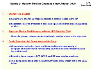
LPK June 2006. Status of Headon Design Changes since August 2005. Shorter Final Doublet : a) Larger bore, shorter SC magnets results in smaller losses in the FD. b) Separator closer to IP results in acceptable parasitic bunch crossing spacing at 46 m.

E N D
LPK June 2006 Status of Headon Design Changes since August 2005 • Shorter Final Doublet: a) Larger bore, shorter SC magnets results in smaller losses in the FD. b) Separator closer to IP results in acceptable parasitic bunch crossing spacing at 46 m. • Separator Electric Field Reduced to Below LEP Operating Field: Allows larger gap between plates resulting in smaller losses in the separator. • Create Space for High Power Intermediate Dump: a) Concentrates extracted beam and beamstrahlung losses mostly at one place and allows room for shielding to protect nearby components and the environment. b) Incoming beam magnets QF3, QD2B, and B2 have smaller apertures. c) This dump is modeled after the aluminum/water 2 MW energy slit in the SLAC A-line.
Plan View of Zero Degree Extraction from IP to Charged Beam Dump
Plan View of Zero Degree Extraction Showing Beamstrahlung Collimation B2 B1 B1 B2 B2 sep γdump QF3 QD2B sep 5 mr dipole septum Int. Dump QD2A
Elevation View of Zero Degree Extraction Showing Beamstrahlung Collimation B1 B1 B2 B2 B2 sep PC Int. Dump Beamstr. Dump QF3 QD2B sep QD2A
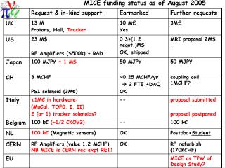
Power Lost, Nominal Parameter Set, 500 GeV CM (kW) dy = 200 nm
Power Lost, Low P Parameter Set, 500 GeV CM (kW) dy = 120 nm can eliminate loss on separator plates with a larger plate gap
Separator breakdown during the bunch train (dipole remains on) Outgoing bunches: 0.5 mrad bend becomes 0.25 mrad bend. Bunches go backward through the incoming beamline and hit the intermediate dump.* Incoming bunches: 0 mrad bend becomes 0.25 mrad bend. Bunches pass through the IP region < 1 cm from the beam axis, go backward through the incoming beamline and hit the intermediate dump.* * The intermediate dump must absorb ≈ 40 bunches before the remainder of the bunch train is switched to the tuneup dump.