Advancements in Geopositioning: Data Collection Strategies by Dr. Ben Peterson and LT Kevin Carroll
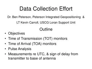
This outline covers the comprehensive objectives and plans for data collection in the field of geopositioning, as coordinated by Dr. Ben Peterson from Peterson Integrated Geopositioning and LT Kevin Carroll from the USCG Loran Support Unit. Key areas of focus include Time of Transmission (TOT) and Time of Arrival (TOA) monitors, pulse analysis, and temporal and spatial variations in ASF and ECD measurements. The goals also include determining the necessity for real-time corrections and exploring effective data collection techniques for various operational scenarios in rugged terrain.

Advancements in Geopositioning: Data Collection Strategies by Dr. Ben Peterson and LT Kevin Carroll
E N D
Presentation Transcript
Data Collection Effort Dr. Ben Peterson, Peterson Integrated Geopositioning & LT Kevin Carroll, USCG Loran Support Unit Outline • Objectives • Time of Transmission (TOT) monitors • Time of Arrival (TOA) monitors • Pulse Analysis • Measurements re UTC, & sign of delay from transmitter to base of antenna
Data Collection – Objectives & Plans • Bound temporal ASF (& ECD) variations • Past USCG data shows largest variations in NE CONUS – area of initial concentration • Determine if real time corrections needed • Determine model to separate correlated & uncorrelated portions of ASF prediction errors • Bound spatial ASF (& ECD) variations • Can regional ASF values be used at runways never calibrated & if so, where? • Use Plumbrook/LSU monitor data, land at airports in the region, collect brief period of stationary data (OU, FAA-TC) • SatMate in TOA mode but not referenced to GPS time • Are there large spatial variations along approaches in rugged terrain? • Do multiple approaches at selected airports (SE Coast of AK?)
Data Collection – Objectives & Plans II • Bound TOT & ECD noise and bias in transmitter • Define what is meant by synchronization to UTC and develop measurement procedures • Delay from installed transformer to base of antenna
TOT & TOA Monitor Network Secondary TOT – Operating Secondary TOT – Planned near term Master TOT – Operating TFE – Jan 03 TOA – Operating TOA – Planned near term TOA - Planned Phase 2 No current plans (SAMs & LORSTAs)
Time of Transmission (TOT) at Secondaries • Discussed at LORIPP I at Stanford 7/25 • Designed, developed, tested, and installed @ 1st site (Nantucket) 3 weeks later. Carolina Beach & Baudette soon after. • Plan to install at other secondaries (Gillette & Grangeville in near future) • Could we get better data if: • We used daily or longer averages of GPS 1 pps vs Cesium to average out multi-path & other GPS errors and/or • We eliminated uncertainty of timing in EPA strobes by using signal from dedicated transformer (either digitized or stop input to TIC)? • Interim only, removed with installation of TFE
Antenna current transformers Digital Averaging O’scope Computer Temporary at antenna base for calibration RS-232 TrueTime XLDC GPS Timing Rcvr Event Time Input Envelope Trigger Circuitry in EPA Permanent TOT Measurement System
Nantucket TOT data 9960M 200 ns time step
Enhanced TOT Measurement System Eliminates EPA circuitry uncertainty Permanently install transformer DSO or TIC Computer RS-232 Trigger/Start TrueTime XLDC GPS Timing Rcvr Event Time Input Cesium Synthesizer& Counter 1 pps 1 pps TIC Enables long term averaging to mitigate GPS error
Present TOA Monitor Discussed at LORIPP II in Portland Operating for past week in Connecticut RF Gate Out LOCUS LRS IIID in TOA mode TrueTime GPS Timing Event Time In RS 232 Computer
Sample TOA data Need to get TOTM data to back out time steps/eliminate steps Large (150-200 ns pp) diurnal variations, could be GPS? 180 ns time step 280 ns time step
Splitter Future TOA Monitors @ SAM sites LOCUS LRS IIID NAVCEN Watchstander RF Gate Out Separate Receiver LOCUS LRS IIID TrueTime GPS Timing Event Time In RS 232 Computer NAVCEN Watchstander RF Gate Out Shared Receiver LOCUS LRS IIID TrueTime GPS Timing Event Time In RS 232 Computer
TOA Monitors w/ Shared Receivers - Options • Option 1: Locus modifies software to allow UPDATE output to be in TOA mode, RPRT format in TD mode • Not till March 03. • UPDATE format is long message which scrolls by watchstander; Is this acceptable? • Cost is $, not LSU time. • Option 2: LSU modifies control software so that receiver can be put in TOA mode • Convert TOA’s to TD’s in both strip charts and raw msg • Requires extensive testing, probably a non-starter • Option 3: Leave receiver in TD mode, TOA monitor software cycles RF gate out among GRI’s tracked • RPRT message may have include lines for signals watchstander doesn’t care about but we do • Will need RS-232 MUX for dual rated PCMS sites • Occasional RF GATE message will scroll on watchstanders screen • N per sample time where N = GRI’s tracked. Sample time = 10-60 minutes. • If message comes when watchstander sending command, both could get garbled
Digital O’scope Pre-Amp Trigger Calibration of TOA Monitor At each SAM RF Gate Out LOCUS LRS IIID in TOA mode In the near far field Calibrate the calibration system by comparing to transmitting antenna current, may be best method to calibrate synchronization of transmitters. Event Time In Pre-Amp Digital O’scope TrueTime GPS Timing Trigger 10 kHz PCI Counter
Pulse Analysis System Antenna Current Transformer Pentium PC w/ICS-650 (12 bit) • Prototype developed & tested at Baudette 5 SEPT, further testing & development @ Boise City 22-24 OCT • Logged TOT, ECD, and Amplitude of each pulse • Logged no raw RF data @ Baudette, Logged raw RF @ Boise City (~40GB) • Processed 2/3 of the PCI’s @ Baudette (one rate only) w/800 MHz P3, 94% w/2 GHz P4 @ Boise City
After Icing (Present SSX has no closed loop control of ECD, new one will and new controllers on old SSXs will as well. I think.)
Mean TOT & ECD as function of pulse number(Present Signal Spec defines sync to UTC by 1st pulse of GRI A, needs changing. TFE is being changed to control average of all 16 pulses)
Example of TOT offset due to Cross Rate(Red: Period = 14.015625 * 96.1ms = 15.015625 * 89.7ms = 1.346902 sec, period for Searchlight = (99.4ms x 96.1 ms)/(99.4ms - 96.1 ms) = 2.89 sec)
From TOTM Manual Issue: ‘+’ sign means signal at transformer earlier than at antenna base. If sign were wrong, Dana would be off by 806 ns, Seneca by 94 ns, etc.
Determination of delay from RF ground return at transmitter to that at antenna base Hardware Diagram for Lessay & Seneca Digital Oscilloscope 100 MHz & 8 bits PCI trigger Ch1 Ch2 Temporary Transformer at base of antenna Transmitter Ground Return Permanently Installed Transformer near Transmitter
Determination of delay from RF ground return at transmitter to that at antenna base • After taking into account all the cable delays • At Lessay: Signal at transmitter was 80 ns later than that at antenna base (i.e. the sign is wrong) • At Seneca: Signal at transmitter was 50 ns earlier than that at antenna base (i.e. the sign is right) • But…. Different cables & transformers, how well are the various delays known?
Determination of delay from RF ground return at transmitter to that at antenna base Hardware Diagram for Boise City Digital Oscilloscope 100 MHz & 8 bits 9610 PCI trigger from TOTM Temporary Transformer One set of measurements @ antenna base, 2nd set adjacent to TOTM transformer Ch1 Ch2 Transmitter Ground Return Permanently Installed TOTM transformer
Transformers adjacent, Ch1 TOTM, Ch2 Temporary, 123 sweeps(Times in usec into record, record started 35 usec before trigger from TOTM or ~10 usec prior to start of pulse)
Illustration of determination of zero crossing(Times in usec re nominal 20 usec point)
Master TOTM Data: 8970 = -560ns, 9960 = -185 ns before, 81 ns after time step 8970-9960 = -375 ns before, -641 ns after time step If sign were wrong and ED correct, 8970-9960 should be in error by over 700 ns. On 9 Oct we (DCN & I) measured 8970X as 280 ns early, TOTM data had Dana 574 ns early, i.e 8970X ED was 200 ns large, assuming this was still true on 2 weeks later, data agrees very well
Master TOTM Data: 8970 = -560ns, 9960 = -185 ns before, 81 ns after time step 8970-9960 = -375 ns before, -641 ns after time step If sign were wrong and ED correct, 8970-9960 should be in error by over 700 ns.
Summary – RF ground return delay • Measurements at Lessay & Seneca not consistent • Measurements at Boise City not conclusive • Signals virtually simultaneous, slightly in direction of TOTM manual, but not at predicted magnitude • Seneca & Dana TOA data strongly suggest the sign is correct • Considering visit to Dana • My opinion: Ability to steer local time scale (<10ns) far exceeds ability to measure TOT relative to that time scale • Cost to improve time transfer to 1ns level not warranted unless data is used as input to UTC time scale • In addition, medium frequency variations (1-20 sec) exist that are not averaged out in user equipment but cannot be eliminated in control loop.
Summary • TOT monitors developed • Baudette, Nantucket & Carolina Beach operating • Grangeville & Gillette next in line • Prototype TOA monitor developed & being tested • Coordinate with LSU & NAVCEN on development of version for SAM sites • Getting good data from pulse analysis system • My opinion: Very limited number of absolute time or cross chain navigation users (maybe 0), larger number of frequency users, large master time steps jeopardize Loran’s ability to meet Stratum 1 requirements.
A final question/live hand grenadeIs the Nome station expected to support NPA’s at Nome Airport?
TOT & TOA Monitor Network Secondary TOT – Operating Secondary TOT – Planned near term Master TOT – Operating TFE – Jan 03 TOA – Operating TOA – Planned near term TOA - Planned Phase 2 No current plans (SAMs & LORSTAs)