Electric Fields and Waves (EFW)
230 likes | 402 Vues
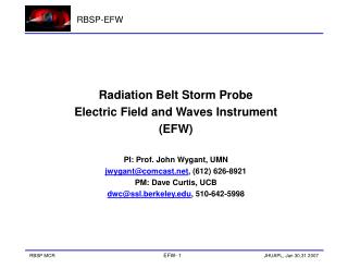
Electric Fields and Waves (EFW). John Wygant EFW PI University of Minnesota. Agenda. Hope. Investigation team Overview Driving requirements Science compliance Primary measurement requirements Design description Interface definition Heritage Changes since MCR

Electric Fields and Waves (EFW)
E N D
Presentation Transcript
Electric Fields and Waves(EFW) John Wygant EFW PI University of Minnesota Radiation Belt Storm Probes MDR
Agenda Hope • Investigation team • Overview • Driving requirements • Science compliance • Primary measurement requirements • Design description • Interface definition • Heritage • Changes since MCR • Technology development plan • Resource summary • Operations concept • Verification & validation • Risks & mitigation • Phase B plans RP-Spice Magnetometer Boom Star Tracker RF Antenna (aft) Shunts (4x) Louvers MagEIS (4x) - [Low, Medium (2x), High] Axial Boom (aft) 1 of 2 SP Wire Boom (4x) RPS Battery Radiator DSAD (2x) REPT Radiation Belt Storm Probes MDR
Investigation Team RBSP EFW PI J. Wygant, UM PM/SE P. Harvey, UCB Science Co-I’s QA R. Jackson, UCB Financial Mgr K. Harps, UCB Subcontracts J. Keenan, UCB Lead Mechanical P. Turin Lead Electrical M. Ludlam Sensors J. Bonnell Signal Processor R Ergun, LASP Ground Systems M. Hashii AXB: R. Duck SPB: G. Dalton Dynamics: D. Pankow Lead : J. Westfall Analog: H. Richard Digital: M. Ludlam FSW: P. Harvey LVPS: P. Berg Radiation Belt Storm Probes MDR
Overview 1 4 5 6 3 2 • RBSP Electric Field Waves Features • Four spin plane booms (2 x 40 m and 2x 50 m) • Two spin axis stacer booms (2x6 m) • Spherical sensors and preamplifiers near outboard tip of boom (400 kHz response) • Flexible boom cable to power sensor electronics & return signals back to SC • Sensors are current biased by instrument command to be within ~ 1 volt of ambient plasma potential. • Main electronic box (filtering, A-D conversion, sensor bias control, burst memory, diagnostics, mode commanding, TM formatting ) • EFW Science quantities include: • • E-fields:(V1-V2, V3-V4, V5-V6) • Interferometric timing: SC-sensor potential (V1s, V2s, V3s, V4s, V5s, V6s) • SC Potential : (V1+V2)/2, (V3+V4)/2 • Interface to EMFISIS instrument • Electrostatic cleanliness spec: variations of potential across spacecraft surfaces smaller than 1 Volt. Radiation Belt Storm Probes MDR
Overview • Science Objective: Measure electric fields associated with a variety of mechanisms causing particle energization, scattering and transport in the inner magnetosphere. • These mechanisms include: • Energization by the large-scale convection E-field . • Energization by substorm injection fronts propagating in from the tail. • Radial diffusion of energetic particles mediated by ULF MHD waves. • Transport and energization by intense magnetosonic waves generated by interplanetary shock impacts upon the magnetosphere. • Coherent and Stochastic acceleration and scattering of particles by small-scale, large-amplitude plasma structures, turbulence and waves (EM and ES ion cyclotron waves, kinetic Alfven waves, lower hybrid, small scale magnetosonic waves,solitary waves, other non-linear structures) • EFW measurements address all 8 of the RBSP science goals with a lesser contribution to goal 6 Radiation Belt Storm Probes MDR
Science Compliance Radiation Belt Storm Probes MDR
Science Compliance Radiation Belt Storm Probes MDR
Primary Measurement Requirements Radiation Belt Storm Probes MDR
SPB Description • Mass: 2.20 kg/unit (4 total). • Envelope: 9.9”H x 4.6”W x 8.6”D. • Deployed Length: 80/100 m tip-to-tip. (47 m cable + 3 m fine wire in each SPB.) • Deploy Rate: 0.5-1.0 cm/s. • Cable Mass Rate: ~3 g/m. • Fine Wire Mass Rate: < 1 g/m. • Preamp Mass: 48 g (up to 150 g w/up-shield and cable driver). • Sphere/Keyreel Mass: 100 g. • Deployed spin MOI: 1920 kg-m2 total • Power: 2.6 W/unit (typ., deploy motor only). • Actuators: Doors are spring-loaded, SMA-released; Cable deploy is motor-driven; no pyros required for actuation. Radiation Belt Storm Probes MDR
AXB Description • Mass: 6.21 kg total (2 booms + tube). • Footprint: 26” H x 6.400” OD inches. • Deployed Length: 13m tip-to-tip. • 0.5-m whip sensor stacer. • Power: 35 W max per boom for release • Actuators: Frangibolt sphere release, main boom release. • Deployment is motor-driven Flight Axial Tube & one AXB from THEMIS Radiation Belt Storm Probes MDR
IDPU Description • Mass: 4.6 kg. • Dimensions: 9.75H x 4.7W x 7.95D inches • Power: 7.8 W CBE. • Elements and Function: • Chassis – provides structural and rad shielding • Backplane – signal and power distribution. • Low-Voltage Power Supply (LVPS) - conversion • Power Controller Board (PCB) – switching • Data Controller Board (DCB) – cmd & telem • Solid State Recorder - data storage • Boom Electronics Board (BEB) – sensor control. • Digital Fields Board (DFB) –signal processing. • EMFISIS Interface – buffering of E & B signals Radiation Belt Storm Probes MDR
Flight Software Description • Development Plan : RBSP_EFW_SW_001 • Heritage : CRRES, Polar, Cluster, THEMIS • Language: 8085 (Harris RH) • Requirements: ~200 • Effort : ~10000 SLOC in 22 modules • Test Platform: ETU • Phases: Board, Box, Inst, Autonomy • Quality : Integrated with Flight Development • Major Functional Elements: • Command Reception & Distribution • Real-Time Data Collection and Playback • On-Board Evaluation for Burst Triggering • Burst Data Collection and Playback • Sine-Wave Fits of E-Field Signal • Delta Mod Compression • Boom Deployment Control Radiation Belt Storm Probes MDR
Interface Definition SPB1 X-Axis IDPU SPB2 COMMANDS SPB3 TELEM Y-Axis SPB4 MAIN +28V SPB Power AXB1 Z-Axis EFW X,Y,Z MAG X,Y,Z AXB Power SCM X,Y,Z AXB2 EMFISIS Radiation Belt Storm Probes MDR
Heritage Spacecraft SPB’s AXB’s Mag Booms S3-2 4 S3-3 4 2 ISEE 2 VIKING 4 FREJA 6 FIREWHEEL* 2 CRRES 2 POLAR 4 2 FAST 4 2 2 CLUSTER I* 16 CLUSTER II 16 THEMIS 20 10 10 SPARES 26 6 2 Lunar Prospector 1 Sounding Rockets ~50 ----- ----- ----- 110 26-76 15 * LV did not achieve orbit Radiation Belt Storm Probes MDR
Major Changes Since MCR • AXB Booms Aligned on Center • AXB Deployed DAD Section is Below Antenna • AXB Sensor Folding Rigid Section (Whip) • AXB Motor Drive for On-Orbit Adjustable Lenth • IDPU Higher Data Allocation • IDPU Added Internal Foldback Limits (Redundant E-Fields) Radiation Belt Storm Probes MDR
New Development Items Boom Deployment Systems Units based on ISEE, CRRES, Polar, FAST, Cluster-II, and THEMIS heritage. Changes will include thinner cable, using SPB-type motor type for AXB instead of brake. Sensor Electronics (Preamp and BEB) Units are based on Polar, Cluster-II, and THEMIS heritage. Changes will include thinner cable, possible cable driver. IDPU Power, DSP, DPU, and Burst Memory Units are based on Polar, FAST and THEMIS heritage. Changes will include interfaces to other instruments and SC, adjustments to filter frequencies and ADC rates, flight software changes. Radiation Belt Storm Probes MDR
Resource Summary CBE (NTE) • Mass: 21.3 (23.6) kg • Power: 7.8 (8.6) W • Telemetry rate: 16.5 (16.5) kbit/sec Radiation Belt Storm Probes MDR
Operations Concept • Commissioning • Draft Deployment Sequence Delivered to APL • Sequence takes appx 2 weeks including science diagnostics • Z-axis adjustment operations are to be decided • Normal operations • Constant Real-Time Data Streaming • Playback of stored events • Bursting • Automatic detection of interesting events • Burst Flag sent to S/C • S/C directed burst events • Command and data handling • Commands determined and sent from UCB • Telemetry distribution at UCB • SOH determination at UCB • SOC Operations will be run from UC Berkeley Radiation Belt Storm Probes MDR
Instrument Verification & Validation Plan EFW Verification Plan (RBSP_EFW_SYS_300) Radiation Belt Storm Probes MDR
S/C Level Instrument V & V Plan EFW Will Support APL’s Verification of Spacecraft EFW Flow Will be as Simple as Possible Expect “Bolt-Hole” Alignments are Sufficient for Boom Systems EFW-EMFISIS Verification Expected to Require Boom Deployment Deployment of Spin Plane Booms and +Z Axial Sensor is Practical at I&T Radiation Belt Storm Probes MDR
Risks and Mitigation 5 L I K E L I H O O D 4 3 2 1 Criticality L x C Trend Approach M – Mitigate W – Watch A – Accept R - Research Decreasing (Improving) Increasing (Worsening) Unchanged New since last month High Med * Low 4 1 5 3 2 1 2 3 4 5 CONSEQUENCES Radiation Belt Storm Probes MDR
Risks and Mitigation Radiation Belt Storm Probes MDR
Phase B Plans • Activities • 06/08 EFW Instrument Requirements Review • 09/08 EFW Instrument Preliminary Design Review • 09/08 EFW SOC Preliminary Design Review • 11/08 Support MPDR • 01/09 SPB ETU Design, Fab & Test • 01/09 AXB ETU Design, Fab & Test • 12/08 IDPU ETU Design, Fab • 12/08 Harness ETU Design, Fabrication • 12/08 S/C – EFW Interface Test (Emulator) Radiation Belt Storm Probes MDR