Download
1 / 53
590 likes | 888 Vues
HVACR318 - Refrigeration. Pump Down Systems Pressure Switches Solenoid Valves. Solenoid Valves. Solenoid Valves are a mechanical/electrical valve. The mechanical part is in the refrigeration or water line. The electrical portion is a coil that is attached to the top of the valve.

E N D
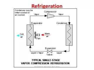
HVACR318 - Refrigeration Pump Down Systems Pressure Switches Solenoid Valves
Solenoid Valves • Solenoid Valves are a mechanical/electrical valve. • The mechanical part is in the refrigeration or water line. • The electrical portion is a coil that is attached to the top of the valve.
Solenoid Valve • The valve in the closed position is not powered and the flow of liquid is being blocked by the plunger in the DOWN position. • In the closed position the coil does not produce any magnetic field as it is not powered.
Solenoid Valve - Closed Valve is blocking flow of liquid.
Solenoid Valve - Open • The valve opens when the coil is powered. • The coil generates a magnetic field and pulls the plunger into the up position. • This allows fluid flow through the central passage of the valve.
Solenoid Valves • In refrigeration solenoid valves mainly have two uses • Hot Gas By-Pass Defrost • Pump Down Systems
Pump Down System • The solenoid in the pump down system is used in the liquid line prior to the metering device and after the receiver. • The solenoid is in the normally closed position. • When the thermostat calls for cooling the solenoid opens.
Pump Down System • This releases refrigerant into the liquid line and raises the pressure of the system. • A pressure switch senses this pressure increase and turns on the compressor. • When the call for cooling is complete the thermostat de-energizes the solenoid
Pump Down System • The solenoid closes and blocks the flow of refrigerant into the liquid line. • The refrigerant gets pumped into the receiver which is mounted after the condenser coil. • Once the refrigerant is pumped down into the receiver the pressure on the system drops.
Pump Down System • Once the pressure has dropped to a pre-determined point the pressure switch opens and shuts off the compressor.
Pump down system • The thermostat controls the solenoid - not the compressor. • The pressure switch controls the compressor. • The purpose of a pump down system is to prevent liquid refrigerant from migrating to the evaporator on off cycles.
Pump down system • If liquid refrigerant is in the evaporator it will be sucked as a liquid into the compressor on start up. • Liquid refrigerant in the compressor can break valves, crank shafts and cause premature compressor failure.
Pump Down Systems • Commercial freezers are low temperature and commercial refrigerators are medium temperature. • Both common to have pump down systems for commercial applications. • Low temp systems • Medium temp systems
Pump Down OFF Cycle EVAPORATOR C 20 CONDENSER 100 OFF MD OFF `
Pump Down Starting Cycle EVAPORATOR C 35 CONDENSER 100 OFF ON MD
Pump Down On Cycle EVAPORATOR C 40 CONDENSER 150 ON ON MD
Pump Down Satisfied Cycle EVAPORATOR C 30 CONDENSER 150 ON OFF MD
Pump Down OFF Cycle EVAPORATOR C 20 CONDENSER 100 OFF MD OFF `
Pump Down Schematic L1 SS N R C S C1 Setpoint: 35 degrees F. Temp is 55 Degree F.
Pressure Switches • Pressure switches are used to start and stop electrical loads such as motors or coils. • Pressure controls contain a bellows, a diaphragm, or a Bourdon tube to create movement when the pressure is changed.
Pressure Switches • When used as a switch the bellows or tube is connected to linkage that operates the electrical contacts. • When used as a valve they operate the valve directly. • The electrical contacts are the components that actually open and close the circuit.
Pressure Switch • The electrical contacts either open or close with a snap action on a rise in pressure. • The pressure switch can also sense a pressure differential and be designed to open or close a set of electrical contacts based on this differential.
Pressure Switch • The pressure control can either be an operating type control or a safety type control. • It can operate either at low or high pressures depending on the type of design.
Pressure Switch • Pressure controls can sometimes be recognized by the small line running to them for measuring fluid pressures. • Pressure switches are manufactured to handle control voltages or line currents to start a compressor up to 3 hp maximum.
Pressure Switch • The high pressure and low pressure controls in the refrigeration and air conditioning industry are the most two widely used pressure controls in the industry.
Pressure Switch • Some pressure switches are adjustable and some are not. • Some controls are automatic reset and some are manual reset. • In some pressure controls the high-pressure and low-pressure controls are built into one housing.
Pressure Switch • The point or pressure setting at which the control interrupts the electrical circuit is known as the cut-out. • The point or pressure setting at which the electrical circuit is made is known as the cut-in. • The difference in the two settings is known as the differential.
Pressure Switch Differential Controls pressure
Pressure Switch Differential Controls temperature through pressure.
Pressure Controls - High • High Pressure controls open on a rise in pressure. • If you hold a high pressure control in your hand at room pressure it is closed. • Primarily used as a safety device to shut off compressor if pressure rise to high.
Pressure Controls - High • Most high pressure controls have a manual reset. • This is to prevent cycling in an unsafe condition.
Pressure Switch - Low • Low pressure switches are used to sense a drop in pressure. • Most often the low switch is used to sense a loss of charge or refrigerant. • The low pressure switch is also used to control the compressor in a pump-down system.
Pressure Switch - Low • It is not desirable to run a system with a low charge because: • The compressor motors use refrigerant to cool the windings. • If the system goes into a vacuum because of a leak it may pull air and noncondensable gases into the system and cause more damage.
Oil Pressure Safety • The oil pressure safety switch is a low and high pressure switch that is a pressure differential control. • The differential control takes the high and low pressure and compares the two numbers coming up with a net pressure.
Oil Pressure Safety • The net oil pressure is the higher number minus the lower number. • The net oil pressure is the useable oil pressure.
Oil Pressure Safety • The oil pressure is caused by a pump attached to the crankshaft of the compressor. • When the compressor is not running there is no oil pressure. • Because of this the oil pressure safety contains a timer that delays the action of the switch for roughly 90 seconds.