Download
1 / 17
400 likes | 1.76k Vues
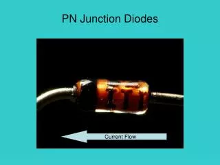
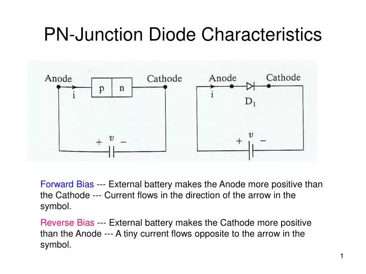
PN-Junction Diode Characteristics. Forward Bias --- External battery makes the Anode more positive than the Cathode --- Current flows in the direction of the arrow in the symbol.

E N D
PN-Junction Diode Characteristics Forward Bias --- External battery makes the Anode more positive than the Cathode --- Current flows in the direction of the arrow in the symbol. Reverse Bias --- External battery makes the Cathode more positive than the Anode --- A tiny current flows opposite to the arrow in the symbol.
Graphical PN-Junction Diode V-I Characteristic Forward Bias Region Reverse Bias Region Reverse breakdown
Ideal PN Junction Diode V-I Characteristic Forward Bias – Short Circuit Reverse Bias – Open Circuit
Diode Reverse Recovery Time ta is the time to remove the charge stored in the depletion region of the junction tb is the time to remove the charge stored in the bulk semiconductor material
Reverse Recovery CharacteristicsSoft Recovery Reverse recovery time = trr = ta+tb Peak Reverse Current =IRR = ta(di/dt)
Reverse Recovery CharacteristicsAbrupt Recovery Reverse recovery time = trr = ta+tb Peak Reverse Current = IRR = ta(di/dt)
Series-Connected Diodes • Use 2 diodes in series to withstand higher reverse breakdown voltage. • Both diodes conduct the same reverse saturation current, Is.
Diode Characteristics • Due to differences between devices, each diode has a different voltage across it. • Would like to “Equalize” the voltages.
Series-Connected Diodes with Voltage Sharing Resistors • Is = Is1+IR1 = Is2+IR2 • IR1 = VD1/R1 • IR2 = VD2/R2 = VD1/R2 • Is1+VD1/R1 = IS2+VD1/R2 • Let R = R1 = R2 • Is1 + VD1/R = Is2 +VD2/R • VD1 +VD2 = Vs
Example 2.3 • Is1 = 30mA, Is2 = 35mA • VD = 5kV • (a) – R1=R2=R=100kΩ, find VD1 and VD2 • (b) – Find R1 and R2 for VD1=VD2=VD/2