Download

1 / 13
130 likes | 140 Vues
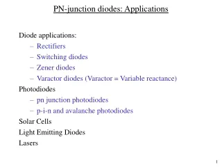
Transient Signals of pn Junction Diodes. Transient Signals of pn Junction Diodes. Transient Signals of pn Junction Diodes. Transient signals caused by buildup of minority carrier charge Must build up charge to turn on pn diode Must remove charge to turn off diode

E N D
Transient Signals of pn Junction Diodes Transient Signals of pn Junction Diodes
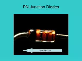
Transient Signals of pn Junction Diodes • Transient signals caused by buildup of minority carrier charge • Must build up charge to turn on pn diode • Must remove charge to turn off diode • Can test transient response by using resistor in series with pn diode Circuit diagram for pn diode time delay measurement.
Transient Signals of pn Junction Diodes Turn on transient: Must build up charge more quickly during transient to turn on diode before voltage relaxes to steady state.
Transient Signals of pn Junction Diodes Turn off transient: Must drop voltage across resistor to discharge current from pn diode.
Transient Signals of pn Junction Diodes • Perform all measurements directly on the oscilloscope • Set function generator to 50 ohm output impedance • Attach black coaxial cable to the function generator • Attach gray coaxial cables to Channel 1 and Channel 2 of the oscilloscope • Use cursors to generate all voltage and time measurements
Transient Signals of pn Junction Diodes • Use Quick Print on oscilloscope to generate waveform output • Plug USB flash drive into oscilloscope USB port • Hit Quick Print on oscilloscope to save waveforms on flash drive • Use this data later in the lab report to demonstrate how you calculated the voltage and time parameters for these waveforms • We will not use scopegrab.vi to analyze data for this lab
Introduction to Lab Equipment Agilent 6000 Series Oscillocope
Transient Signals of pn Junction Diodes Turn on measurements: • IF = (VCh2,ss – VCh1,ss)/R • Vpk - Vss • tfr Turn off measurements: • Vss – Voff • trd Measured data for the turn on and turn off transients for square wave at 20 kHz Plot waveforms at a particular voltage to demonstrate how you calculated IF and the relevant voltage and time parameters for the turn on and turn off transients
Transient Signals of pn Junction Diodes Turn on and turn off transients generated from a 2.5 V to 0 V voltage transition on Channel 1 and Channel 2 (left) and measurements used to generate IF (right).
Transient Signals of pn Junction Diodes Voltage and time measurements taken for turn on (top) and turn off (bottom) voltage transients generated between 2.5V to 0 V.
Transient Signals of pn Junction Diodes Positive to negative transient: First reverse biases resistor to rapidly discharge current from pn diode during tsd before diode begins to approach reverse saturation current causing a rapid drop in voltage towards end of trr.
Transient Signals of pn Junction Diodes Measurements: • VF • IF = VCh1/R • VR • IR = VCh1/R • tsd • trr Measured data for positive to negative transient for square wave at 20 kHz Plot the waveform at a particular voltage to demonstrate how you calculated the relevant voltage and time parameters for the reverse recovery transients
Transient Signals of pn Junction Diodes Voltage (top) and time (bottom) measurements taken for the reverse recovery transient generated from a 0.9 V to -0.5 V transition.