Download
1 / 25
260 likes | 268 Vues
Steven Rogacki Senior Engineer in Research SPRL: Space Physics Research Laboratory Office: 1204 Space Physics Bldg. (734)936-3104 rogacki@umich.edu. Engineering of Embedded Systems. SPRL Engineering.

E N D
Steven Rogacki Senior Engineer in Research SPRL: Space Physics Research Laboratory Office: 1204 Space Physics Bldg. (734)936-3104 rogacki@umich.edu Engineering of Embedded Systems
SPRL Engineering SPRL provided multiple electronic assemblies for SAM, the primary instrument suite on the NASA/MSL Rover mission Also built electronics for: • MAVEN (Mars Atmosphere and Volatile EvolutioN) • LADEE (Lunar Atmosphere & Dust Environment Explorer) • CASSINI/Huygens probe • Rosetta (Comet rendezvous) • Solar Orbiter • Remote sensing radiometry: SMAP, GeoSTAR, HIRad, LRR FIPS Mass Spectrometer, Mercury Orbiter Electronics Box, incl: +15kV swept, -15kV adjustable and +3.6kV adjustable power supplies; digital and Analog signal processing ASPS automatic precipitation sampling system PENGUIN Polar magnetometer SPRL designed and built the TIDI Instrument on theTIMED spacecraft. Still taking wind speed data after 14 years in orbit Design of Space systems involves some unique constraints: thermal (vacuum operation); radiation environment; launch vibration; limited parts choices; hard delivery schedules, no service calls
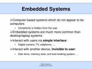
Embedded Systems • Have limited or specific functionality • Are not general purpose computers, but they are programmed... • ASIC (generally high volume) • FPGA - Field Programmable Gate Array • Microcontroller • Limited user interface if any • “Real-time” response is often critical
Embedded Systems • Discuss: • Practical design methods and avoiding problems • Power Supplies for embedded systems Linear vs. Switching • Terminology • Introduction to SPICE Modelling • Online resources • Real-life examples • Note to self: slides with pictures are better
A Real Design Process is often (usually) chaotic System Requirements Poorly defined requirement System Requirements Spec can't be met Analysis Analysis Oops, we forgot something Real parts don't Work that way Electrical Schematic Electrical Schematic Not enough memory I can't test this at all PC Board Layout Mechanical Design PC Board Layout Mechanical Design How can I test this? Fabricate Fabricate Program & Test Program & Test This is more realistic and you aren't doing anything wrong... Try to anticipate problems, be suspicious of “small changes”, do trade studies, build limited prototypes to test uncertainties, begin programming early, revise documentation as you go, keep a lab notebook. This framework can help to schedule milestones
Design Process: System Requirements Determine what you are trying to do... Document Functional Requirements: To design a system with ambiguous specifications, write your own and update as needed. Requirements must be testable or verifiable through analysis. “Fast as possible”, “Low noise”, “Small size”, etc. are NOT requirements. Block diagrams can be helpful to keep a global view. Most practical designs progress from the top down AND from the bottom up. Simple Top Level Functional Block Diagram (FIPS Mass Spectrometer)
Block Diagram showing interface details(PENGUIN Polar Magnetometer)
Design Process • Analysis and Simulation Information collection phase: study the problem, gather information, consider alternatives. Dig deeper into the real goals. Create or reference top-level and detailed requirements. Meet and discuss. Find examples of similar designs. • Design Tools • MATLAB, Mathematica, Excel (license free: Octave, SciLab) • SPICE (license free: LtSPICE, more on this later...) • Development Boards: low cost way to test possible designs • Prototype boards: The goal is to test ideas with speed and flexibility • Online tools: use parametric parts searches on device producers websites. Linear Technology, Analog Devices, National Semiconductor, Texas Instruments, STMicro, Microchip, Microsemi, Micrel, Maxim, OK that's enough but of course there are others... • Most of these companies also produce Application Notes and Reference Designs for their parts. Always use these if you can.
Application Notes • A wealth of information from many companies. For example, Linear Technology AN47 discusses high speed analog circuits; how to accurately measure them, layout advice, numerous examples, and how to successfully build fast prototype circuits. The terse comments on the pages shown here are a bit of engineering humor.
One Prototyping Method • Printed circuit boards are relatively low cost and can be produced in less than a week; they can be an efficient prototyping tool if you can afford multiple iterations. • But, if you are inventing something new, the proper circuit design may not be known. The technique shown here is good for testing high speed analog circuitry, allowing very rapid component or topology changes. Keep a hot soldering iron handy.
Design Process • Electrical Schematic Design • An electrical schematic diagram is not just a means of capturing a design. It should also clearly communicate the design functionality. • Signals generally progress from left to right, (+) Power feeds in at the top, (-) Power at the bottom. Named nets should be used to limit clutter and identify signals across sheets, but don't create a graphical netlist. • Tools include: ORCAD, Altium, Eagle (free: KiCAD) • The Art of Electronics, 2nd ed. Horowitz, Hill, is another wonderful resource for practical advice. One example from that book: An awful schematic A good schematic
A reasonably good schematic LT1964, LT1461 LDO's provide +/-1.5V, +1.8V (Low Dropout Regulators)
Schematic Examples • Showing an embedded power supply providing multiple voltages with both linear and switching regulators. • Outputs: +15V (unregulated), +5V, +3.3V, +1.2V using LT3502A (switcher) and LTC1844 (LDO regulator) • Snow Sensor
Design Process: Circuit Board Layout • Bypass capacitors for every IC, as near to the chip as possible. Datasheets usually offer specific recommendations for bypassing and sometimes board layouts. • Minimize inductance of high frequency or sensitive signal traces. Inductance is a function of the enclosed circuit path area. • High frequency signals may need controlled impedance transmission lines or even differential paired conductors. • A ground plane layer is recommended for all but the simplest designs. • Consider where to add test points. PCB Calculator
Design Process: Mechanical Design; Fabrication and Assembly • Don't forget a Bill of Material • Schematic capture tools can create BOM reports • Include Component type; description; Manufacturer and Part number; Reference designation; Package; voltage, tolerance, or power rating if needed; if possible, distributor and their part number. • 3D Modelling is extremely useful: • Befriend a mechanical engineer, or • Learn Autocad Inventor, Solidworks, or an equivalent • This class will introduce you to bench reflow soldering for circuit board assembly. There is also hand soldering; not as easy as it looks. • Some parts will likely require specialized equipment, eg. Ball Grid Arrays. Services are available which will assemble your boards for reasonable cost. They may even buy all the electronic parts as well (Advanced Assembly is one such vendor)
Design Process Specifics: Power Subsystem • Specified Power Sources: If you are designing a subsystem in a larger assembly, your primary power source may be specified for you: • DC Bus voltage; There may be inrush current limits or even conducted noise limits in addition to specified voltage range, current range, and power limits. • AC Line voltage; Chips exist which can regulate rectified 120VAC. • Alternative embedded power sources • Solar Cells: Will almost certainly require a battery system as well... • PPT (Peak Power Tracking) may be needed using a switching power supply. • Battery - Primary cell or rechargeableExample: Li-Ion Rechargeable Battery • Huge variety of types: besides energy capacity and cell voltage, consider internal resistance, peak or pulse current required, temperature range in operation, safety, discharge characteristics. Rechargeable batteries or battery packs can have charge monitors build-in to protect the battery or balance charge in series cells. • Energy harvesting: Use vibration, thermal, light, sound, but get very low power: supercap can replace need for battery.
Primary battery datasheet (non-rechargeable). • Capacity 2000mAH meets the 1547mAH calculation. • But, this battery won't work for the Snow Sensor project. • Any guesses why? alternate battery
Once the primary power source is defined, all subsystem load voltage and current requirements are specified, and other factors considered such as voltage stability, response to transient loads and desired efficiency, actual part selection for voltage regulation can begin. Some terminology: • Quiescent Current: the current or power that the regulator uses to function; does not flow to the load. • Dropout Voltage: minimum voltage between input and output • Linear Voltage Regulator: Non-LDO Devices usually capable of higher current • LDO Low Drop-Out Regulator • Voltage Reference: High accuracy voltage control, can sink as well as source current • Switching Regulator: More efficient for higher currents or large difference between input and output voltages. • Buck: Output voltage lower than input • Boost: Output voltage higher than input • Buck/Boost: Input voltage can range above and below output • Resonant: Many topologies, higher power. • Peak Power Tracker: get maximum power out of a solar array • Application note: Linear Technology AN140 has a good description of linear and switcher supplies
Design Process Specifics: Power Subsystem To paraphrase AN140: The choice between switcher and linear supply is not always easy, but linear regulators or LDO's are often selected for their simplicity, ease of use, low cost, low noise, and fast transient response. And if Vout is close to Vin, an LDO may be more efficient than a SMPS (switching mode power supply).
Testing Notes • Write firmware with testing in mind. Include low-level test commands for every function. • When making direct circuit measurements, understand 'scope probes and their limitations: Another diagram from Linear Technology AN47 >>>>> • The higher the frequency, the shorter the probe ground lead. • Adjust probe response before using. • Oscilloscopes are fast and show waveforms but are not very accurate for amplitude measurement. Use appropriate bench instrumentation.
Introduction to SPICE • Demonstrate capabilities using linear regulator model. • Show how to test specific (Linear Technology) voltage regulators • LDO Linear Regulator LTC1844 for transient response • Switching buck converter LT3502 for noise and efficiency • Questions?