Download
1 / 57
630 likes | 971 Vues
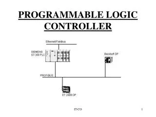
Chapter 7. PROGRAMMABLE LOGIC CONTROLLER. Mr. Mohamed Abdullah BLESSTRONIX Puducherry. 1) on-off control, 2) sequential control, 3) feedback control, and 4) motion control. FUNCTIONS OF CONTROLLERS. 1) mechanical control - cam, governor, etc.,

E N D
Chapter 7. PROGRAMMABLELOGIC CONTROLLER Mr. Mohamed Abdullah BLESSTRONIX Puducherry
1) on-off control, 2) sequential control, 3) feedback control, and 4) motion control. FUNCTIONS OF CONTROLLERS
1) mechanical control - cam, governor, etc., 2) pneumatic control - compressed air, valves,etc. 3) electromechanical control - switches, relays, a timer, counters, etc, 4) electronics control - similar to electromechanical control, except uses electronic switches. 5) computer control. CONTROL DEVICES
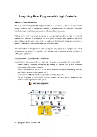
"A digitally operating electronic apparatus which uses a programmable memory for the internal storage of instructions by implementing specific functions such as logic sequencing, timing, counting, and arithmetic to control, through digital or analog input/output modules, various types of machines or processes. The digital computer which is used to perform the functions of a programmable controller is considered to be within this scope. Excluded are drum and other similar mechanical sequencing controllers." PROGRAMMABLE LOGIC CONTROLLER Invented in 1968 as a substitute for hardwired relay panels. National Electrical Manufacturing Association (NEMA)
MODICOM - GOULD ALLEN-BRADLEY GE SQUARE-D etc. VENDORS
PLC Input CPU Input Module Flag System Output Module Output User Ladder Diagram Working memory registers
An Large Size PLC • The main module measures 19” x 20” x 14.5”. • have upto 10,000 I/O points • supports all functions • expansion slots to accommodate PC and other communication devices.
A Small Size PLC • Measures 4.72”x 3.15” x 1.57”. • 32 I/O points • Standard RS 232 serial communication port
SWITCHES L o c k i n g N o n - l o c k i n g N o r m a l l y O p e n N o r m a l l y C l o s e d DPST P 1 SPDT P 2 M u l t i p l e P o l e M u l t i p l e T h r o w M a k e - b e f o r e - b r e a k B r e a k - b e f o r e - m a k e
Throw - number of states Pole - number of connecting moving parts (number of individual circuits). SPDT TERMS A serial switch box (A-B box) has two 25 pin serial ports to switch from. A B Output Input DPST Knob How is this switch classified?
Selector switches Pushbutton switches Photoelectric switches Limit Switches Proximity switches Level switches Thumbwheel switches Slide switches TYPES OF SWITCHES • RATING: • 24 Volts AC/DC • 48 Volts AC/DC • 120 Volts AC/DC • 230 Volts AC/DC • TTL level • (Transistor-to-transistor • ±5V) • Isolated Input
RELAYS A switch whose operation is activated by an electromagnet is called a "relay" contact coil input Relay coil R1 Output contact R1
Digital counters output in the form of a relay contact when a preassigned count value is reached. COUNTER 5
A timer consists of an internal clock, a count value register, and an accumulator. It is used for or some timing purpose. TIMER Time 5 seconds.
For a process control, it is desired to have the process start (by turning on a motor) five seconds after a part touched a limit switch. The process is terminated automatically when the finished part touches a second limit switch. An emergency switch will stop the process any time when it is pushed. AN EXAMPLE OF RELAY LOGIC
Programmable controllers replace most of the relay panel wiring by software programming. PLC ARCHITECTURE A typical PLC
1. Processor Microprocessor based, may allow arithmetic operations, logic operators, block memory moves, computer interface, local area network, functions, etc. 2. Memory Measured in words. ROM (Read Only Memory), RAM (Random Access Memory), PROM (Programmable Read Only Memory), EEPROM (Electric Erasable Programmable ROM), EPROM (Erasable Programmable Read Only Memory), EAPROM (Electronically Alterable Programmable Read Only Memory), and Bubble Memory. PLC COMPONENTS
3. I/O Modular plug-in periphery AC voltage input and output, DC voltage input and output, Low level analog input, High level analog input and output, Special purpose modules, e.g., high speed timers, Stepping motor controllers, etc. PID, Motion 4. Power supply AC power 5. Peripheral hand-held programmer (HHP) CRT programmer operator console printer simulator EPROM loader graphics processor network communication interface modular PC PLC COMPONENTS
AC Voltage I/O DC Voltage I/O numerical input and output special-purpose modules, for example, high-speed timers, and stepping motor controllers Discrete I/O
Analog inputs: Flow sensors Humidity sensors Potentiometers Pressure sensors Temperature sensors Analog outputs: Analog meters Analog valves and actuators DC and AC motor drives Analog I/O
Thermocouple input Low level analog signal, filtered, amplified, and digitized before sending to the processor through I/O bus. Fast input 50 to 100 microsecond pulse signal detection. ASCII I/O Communicates with ASCII devices. Stepper motor output Provide directly control of a stepper motor. Servo interface Control DC servo motor for point-to-point control and axis positioning. PID control The Proportional Integral Derivative is used for closed loop process control. Network module Some Special I/O
A ladder diagram (also called contact symbology) is a means of graphically representing the logic required in a relay logic system. LADDER DIAGRAM Rail Rung
PLC WIRING DIAGRAM Output Input PLC A 11 01 C 01 02 20 B 12 02 20 03 11 20 External switches Stored program
Input Connections AC DC TTL
Output Connections AC DC TTL
A PLC resolves the logic of a ladder diagram (program) rung by rung, from the top to the bottom. Usually, all the outputs are updated based on the status of the internal registers. Then the input states are checked and the corresponding input registers are updated. Only after the I/Os have been resolved, is the program then executed. This process is run in a endless cycle. The time it takes to finish one cycle is called the scan time. In some controllers the idle state is eliminated. In this case, the scan time varies depends on the program length. Output Input begin Idle Scan cycle Resolve logic SCAN
Ladder Diagram - most common Structure Text Programming (ST) Functional Block Programming (FB) Instruction List (IL) Sequential Function Chart (SFC) PLC Programming
1) Relay, 2) Timer and counter, 3) Program control, 4) Arithmetic, 5) Data manipulation, 6) Data transfer, and 7) Others, such as sequencers. PLC Ladder DiagramINSTRUCTIONS
ON : TRUE, contact closure, energize, etc. OFF: FALSE, contact open , de-energize, etc. LOGIC STATES Do not confuse the internal relay and program with the external switch and relay. Internal symbols are used for programming. External devices provide actual interface. (In the notes we use the symbol "~" to represent negation. AND and OR are logic operators. )
AND and OR LOGIC PB2 R1 PB1 R1 = PB1.AND.PB2 AND PB4 PB3 R2 R2 = PB2.AND.~PB4 R1 PB1 R1 = PB1 .OR. PB2 OR PB2
COMBINED AND & OR R1 = PB1 .OR. (PB2 .AND. PB3) R1 PB1 PB2 pb3
Contacts: a. Normally open -| |- b. Normally closed -|/|- c. Positive transition sensing -|P|- d. Negative transition sensing -|N|- Coil: a. Coil -( )- b. negative coil -(/)- c. Set Coil -(S)- d. Reset Coil -(R)- RELAY A Relay consists of two parts, the coil and the contact(s). ( )
Relay (continue) Coil: e. Retentive memory Coil -(M)- f. Set retentive memory Coil -(SM)- g. Reset retentive memory Coil -(RM)- h. Positive Transition-sensing Coil -(P)- h. Negative Transition-sensing Coil -(N)- (set coil latches the state, reset coil deenergize the set coil. retentive coil retain the state after power failure.)
Timers: a. Retentive on delay -(RTO)- b. Retentive off delay -(RTF)- c. Reset -(RST)- Counter: a. Counter up -(CTU)- b. Counter down -(CTD)- c. Counter reset -(CTR)- TIMERS AND COUNTERS Input True False True RTO counting stop counting resume RTF stop counting stop RTO reach PR value, output ON RTF reach PR value, output OFF PR value in 0.1 second
Output Step A B C Dwell time 1 ON OFF OFF 5 sec. 2 ON ON OFF 10 sec. 3 OFF OFF ON 3 sec. 4 OFF ON OFF 9 sec. SEQUENCER Sequencers are used with machines or processes involving repeating operating cycles which can be segmented into steps.
I/O points are numbered, they correspond to the I/O slot on the PLC. For A-B controller used in our lab I/O uses 1-32 Internal relays use 033 - 098 Internal timers/counters/sequencers use 901-932 Status 951-982 A-B PLC
id description state explanation MSI microswitch 1 part arrive R1 output to bar code reader 1 scan the part C1 input from bar code reader 1 right part R2 output robot 1 loading cycle R3 output robot 1 unloading cycle C2 input from robot 1 robot busy R4 output to stopper 1 stopper up C3 input from machine 1 machine busy C4 input from machine 1 task complete PROGRAMMING EXAMPLE 1
Rung 1. If part arrives and no part is stopped, trigger the bar code reader. Rung 2. If it is a right part, activate the stopper. Rung 3. If the stopper is up, the machine is not busy and the robot is not busy, load the part onto the machine. Rung 4. If the task is completed and the robot is not busy, unload the machine. SOLUTION
a high level language used to express the behavior of functions, function blocks and programs In IEC 1131-3 standard, it has a syntax very similar to PASCAL strongly typed language Functions: assignments expressions statements operators function calls flow control Structured Text Programming
Data Types SINT short integer 1 byte INT integer 2 bytes DINT double integer 4 bytes LINT long integer 8 bytes USINT unsigned short integer 1 byte UINT unsigned integer 2 bytes UDINT unsigned double integer 4 bytes ULINT unsigned long integer 8 bytes REAL real 4 bytes LREAL long real 8 bytes TIME time duration DATE calendar date TOD time of day DT date and time of day STRING character strings BOOL boolean 1 bit BYTE byte 1 byte WORD 16 bit bit string 16 bits DWORD 32 bit bit string 32 bits LWORD 64 bit bit string 64 bits
Derived Data Types TYPE (* user defined data types, this is a comment*) pressure : REAL; temp : REAL; part_count : INT; END_TYPE; Structure: TYPE data_packet: STRUCT input : BOOL; t : TIME; out : BOOL; count : INT; END_STRUCT; END_TYPE;
Variable Declarations Local variable: Use VAR, VAR_INPUT, VAR_OUTPUT, VAR_IN_OUT, VAR_GLOBAL, VAR_EXTERNALfor different variable types. VAR I,j,k : INT; v : REAL; END_VAR
( ) parenthesized expression function( ) function ** exponentiation - negation NOT Boolean complement + - * / math operators MOD modulus operation < > <= >= comparison operators = equal <> not equal AND, & Boolean AND XOR Boolean XOR OR Boolean OR Operators and Expressions Y := X+1.0; y := a AND b; v := (v1 + v2 + v3)/3 output := (light = open) OR (door = shut);
IF a > 100 THEN redlight := on; ELSEIF a > 50 THEN yellowlight := on; ELSE greenlight := on; END_IF; Condition Statements CASE dial_setting OF 1 : x := 10; 2 : x := 15; 3 : x := 18; 4,5: x := 20; (* 4 or 5 *) ELSE x := 30; END_CASE
FOR I:= 0 to 100 BY 1 DO light[I] := ON; END_FOR I := 0; WHILE I < 100 DO I := I + 1; light[I] := on; END_WHILE Iteration Statements I := 0; REPEAT I := I + 1; light[I] := on; UNTIL I > 100; END_REPEAT
FUNCTION add_num : REAL VAR_INPUT I,J : REAL END_VAR add_num := I + J; END_FUNCTION Call a function: x:= add_num(1.2, 5.6); Built-in Functions: ABS, SQRT, LN, LOG, EXP, SIN, COS, TAN, ASIn, ACOS, ATAN, ADD, MUL, SUB, DIV, MOD, EXPT, MOVE), logic functions (AND, OR, XOR, NOT), bit string functions (SHL, SHR shift bit string left and right , ROR, ROL rotate bit string), etc. Functions
PROGRAM example7.1 VAR_INPUT MSI : BOOL; C1 : BOOL; C2 : BOOL; C3 : BOOL; C4 : BOOL; END_VAR VAR_OUTPUT R1 : BOOL : FALSE; R2 : BOOL : FALSE; R3 : BOOL : FALSE; R4 : BOOL : FALSE; END_VAR Programs R1 := MS1 AND (NOT R4); R2 := R4 AND (NOT C3) AND (NOT C2); R3 := C4 AND (NOT C3); R4 := C1; END_PROGRAM
Functional block (FB) is a well packaged element of software that can be re-used in different parts of an application or even in different projects. Functional blocks are the basic building blocks of a control system and can have algorithms written in any of the IEC languages. Functional Block Programming
An Up Counter Function Block The algorithm in StructuredText: FUNCTION BLOCK CTU VAR_INPUT CU : BOOL; R : BOOL; PV : INT; END_VAR VAR_OUTPUT Q : BOOL; CV : INT; END_VAR IF R THEN CV := 0; ELSEIF CU AND (CV < PV) THEN CV := CV + 1; END_IF; Q := (CV >= PV); END_FUNCTION_BLOCK CU : input to be counted R : reset PV : preset value Q : contact output CV : counter value.