Download
1 / 37
4.18k likes | 8.7k Vues
Programmable Logic Controller (P L C ). Muhajir Ab. Rahim School of Mechatronic Engineering UniMAP. Brief PLC History. The PLC was invented in response to the needs of the American automotive industry .

E N D
Programmable Logic Controller (PLC) Muhajir Ab. Rahim School of Mechatronic Engineering UniMAP
Brief PLC History • The PLC was invented in response to the needs of the American automotive industry. • Before the PLC, control, sequencing, and safety interlock logic for manufacturing automobiles was accomplished using relays, timers and dedicated closed-loop controllers. • The process for updating such facilities for the yearly model change-over was very time consuming and expensive, as the relay systems needed to be rewired by skilled electricians. • In 1968 GM Hydramatic (the automatic transmission division of General Motors) issued a request for proposal for an electronic replacement for hard-wired relay systems.
Brief PLC History • The winning proposal came from Bedford Associates of Boston, Massachusetts. • The first PLC, designated the 084 because it was Bedford Associates eighty-fourth project, was the result. Bedford Associates started a new company dedicated to developing, manufacturing, selling, and servicing this new product: Modicon, which stood for MOdular DIgital CONtroller. • One of the people who worked on that project was Dick Morley, who is considered to be the "father" of the PLC. • The Modicon brand was sold in 1977 to Gould Electronics, and later acquired by German Company AEG and then by Schneider Electric, the current owner.
Disadvantages of Classic control panel • Large amount of work required connecting wires • 2. Difficulty with changes or replacements • 3. Difficulty in finding errors; requiring skillful/experienced work force • 4. When a problem occurs, hold-up time is indefinite, usually long
Introduction • What is PLC? PLC is an industrial computer control system that continuously monitors the state of input devices and makes decisions based upon a custom program to control the state of output devices
Definition A formal definition of a PLC comes from the National Electrical Manufacturers Association (NEMA): A digitally operating electronic apparatus which uses a programmable memory for the internal storage of instructions for implementing specific functions such as logic, sequencing, timing, counting, and arithmetic to control, through digital or analog input/output modules, various types of machines or processes.
PLC Overview • A PLC has many "input" terminals, through which it interprets "high" and "low" logical states from sensors and switches. • It also has many output terminals, through which it outputs "high" and "low" signals to power lights, solenoids, contactors, small motors, and other devices lending themselves to on/off control. • In an effort to make PLCs easy to program, their programming language was designed to resemble ladder logic diagrams. • Thus, an industrial electrician or electrical engineer accustomed to reading ladder logic schematics would feel comfortable programming a PLC to perform the same control functions.
Input Output Input Output
The program takes the place of much of the external wiring that would be required for control of a process. Advantages of a PLC Control System Eliminates much of the hard wiring that was associated with conventional relay control circuits.
Example • Lets say that two push buttons, PB1 and PB2, are connected to a PLC. • Two pilot lights, PL1 and PL2, are also connected to the PLC. • The way these devices are connected now pressing push button PB1 turns on pilot light PL1 and pressing push button PB2 turns on pilot light PL2. • Lets say that you want to change this around so that PB1 controls PL2 and PB2 controls PL1. • In a traditional system, you would have to rewire the circuit so that the wiring from the first push button goes to the second pilot light and vice versa. • However, because these devices are connected to a PLC, making this change is as simple as making a small change in the control program.
Since all the logic is contained in the PLC’s memory, there is no chance of making a logic wiring error. Advantages of a PLC Control System Increased Reliability: Once a program has been written and tested it can be downloaded to other PLCs.
It is easier to create and change a program in a PLC than to wire and rewire a circuit. End-users can modify the program in the field. Advantages of a PLC Control System More Flexibility: Original equipment manufacturers (OEMs) can provide system updates for a process by simply sending out a new program.
Generally, if an application requires more than about 6 control relays, it will usually be less expensive to install a PLC. Advantages of a PLC Control System Lower Costs: Originally PLCs were designed to replace relay control logic. The cost savings using PLCs have been so significant that relay control is becoming obsolete, except for power applications.
They can be networked to perform such functions as: supervisory control, data gathering, monitoring devices and process parameters, and downloading and uploading of programs. Advantages of a PLC Control System Communications Capability: A PLC can communicate with other controllers or computer equipment.
Machines that process thousands of items per second and objects that spend only a fraction of a second in front of a sensor require the PLC’s quick response capability. Advantages of a PLC Control System Faster Response Time: PLCs operate in real-time which means that an event taking place in the field will result in an operation or output taking place.
The control program can be watched in real-time as it executes to find and fix problems Advantages of a PLC Control System Easier To Troubleshoot: PLCs have resident diagnostic and override functions that allows users to easily trace and correct software and hardware problems.
Others PLC Brands • Others well known PLC brands are ABB Ltd., Koyo, Honeywell, Modicon, Allen-Bradley, Tesco Controls and Panasonic (Matsushita)
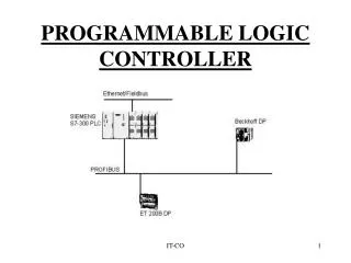
PLC Hardware • PLC hardware falls into two physical configurations: 1) Fixed- has all of its components (input section, CPU, memory, power supply, output section) built into one self-contained unit, and are not removable. 2) Modular- comes as separate pieces of power supplies, CPU, input and output cards or I/O modules. * flexibility
PLC System • A PLC system consists of a Central Processing Unit (CPU) containing an application program and Input and Output Interface modules, which is directly connected to the field I/O devices. The program controls the PLC so that when an input signal from an input device turns ON, the appropriate response is made. The response normally involves turning ON an output signal to some sort of output devices. • The Central Processing Unit (CPU) is a microprocessor that co-ordinates the activities of the PLC system. It executes the program, processes I/O signals & communicates with external devices.
There are various types of memory unit. It is the area that holds the operating system and user memory. The operating system is actually a system software that co-ordinates the PLC. Ladder program. Timer and Counter Values are stored in the user memory. Depending on user’s need, various types of memory are available for choice: (a) Read —Only Memory (ROM) ROM is a non-volatile memory that can be programmed only once. It is therefore unsuitable. It is least popular as compared with others memory type. (b) Random Access Memory (RAM) RAM is commonly used memory type for storing the user program and data. The data in the volatile RAM would normally be lost if the power source is removed. However, backing up the RAM with a battery solves this problem. (c) Erasable Programmable Read Only Memory (EPROM) EPROM holds data permanently just like ROM. It dose not require battery backup. However, exposing it to ultraviolet light can erase its content. A prom writer is required to reprogram the memory. (d) Electrically Erasable Programmable Read Only Memory (EEPROM) EEPROM combines the access flexibility of RAM and the non-volatility of EPROM in one. Its contents can be erased and reprogrammed electrically, however, to a limit number of times.
Input Devices • Intelligence of an automated system is greatly depending on the ability of a PLC to read in the signal from various types of automatic sensing and manual input field devices. • Push buttons, keypad and toggle switches, which form the basic man-machine interface, are types of manual input device. • On the other hand, for detection of work piece, monitoring of moving mechanism, checking on pressure and or liquid level and many others, the PLC will have to tap the signal from the specific automatic sensing devices like proximity switch, limit switch, photoelectric sensor, level sensor and so on. • Types of input signal to the PLC would be of ON/OFF logic or analogue. These input signals are interfaced to PLC through various types of PLC input module.
Output Devices • An automatic system is incomplete and the PLC system is virtually paralyzed without means of interface to the field output devices. • Some of the most commonly controlled devices are motors, solenoids, relays indicators, buzzers and etc. • Through activation of motors and solenoids the PLC can control from a simple pick and place system to a much complex servo positioning system. These type of output devices are the mechanism of an automated system and so its direct effect on the system performance. • However, other output devices such as the pilot lamp, buzzers and alarms are merely meant for notifying purpose. Like input signal interfacing, signal from output devices are interfaced to the PLC through the wide range of PLC output module.
Programming Devices • The programming device is used to input the desired instructions. These instructions determine what the PLC will do for a specific input • The PLC can be programmed by; 1) Personal Computer (PC programming device) 2) Programming Console (Hand held programming device)
PC Programming Device • Manufacturers software required. • Large amounts of logic can be displayed. • Circuit elements can be highlighted in color to indicate status. • More than one program can be stored on the computers hard drive • The computer can be used to document the program. • PC software provides cut-and-paste features for program developing and editing. • Allows easy monitoring of data tables. • Easy to make copies of the program on floppy disk,CD-ROM, or hard drive
Hand Held Programming Device • Has a connecting cable so that it can be plugged into a PLC programming port. • Are compact, inexpensive, and easy to use. • Contains keys for instruction entering and editing, and navigation keys for moving around the program
PLC Operation • A PLC works by continually scanning a program. We can think of this scan cycle as consisting of 3 important steps CHECK INPUT STATUS EXECUTE PROGRAM UPDATE OUTPUT STATUS
PLC Operation • Step 1 -CHECK INPUT STATUS-First the PLC takes a look at each input to determine if it is on or off. In other words, is the sensor connected to the first input on? How about the second input? How about the third... It records this data into its memory to be used during the next step. • Step 2- EXECUTE PROGRAM-Next the PLC executes your program one instruction at a time. Maybe your program said that if the first input was on then it should turn on the first output. Since it already knows which inputs are on/off from the previous step it will be able to decide whether the first output should be turned on based on the state of the first input. It will store the execution results for use later during the next step. • Step 3- UPDATE OUTPUT STATUS-Finally the PLC updates the status of the outputs. It updates the outputs based on which inputs were on during the first step and the results of executing your program during the second step. Based on the example in step 2 it would now turn on the first output because the first input was on and your program said to turn on the first output when this condition is true. • After the third step the PLC goes back to step one and repeats the steps continuously. One scan time is defined as the time it takes to execute the 3 steps listed above.