Download
1 / 15
170 likes | 225 Vues
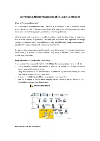
The Programmable Logic Controller. Program. Input Data. Processing. Output Data. Basic Principle of a PLC. Components of a PLC. A PLC is made up of two basic sections Central Processing Unit (CPU) Input/Output (I/O) Interface CPU consists of three main parts Processor Memory

E N D
Program Input Data Processing Output Data Basic Principle of a PLC
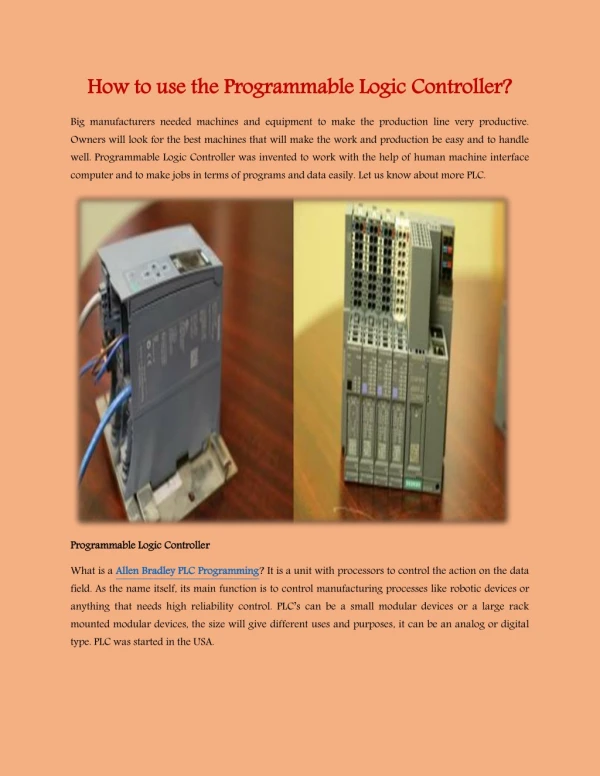
Components of a PLC • A PLC is made up of two basic sections • Central Processing Unit (CPU) • Input/Output (I/O) Interface • CPU consists of three main parts • Processor • Memory • Power Supply
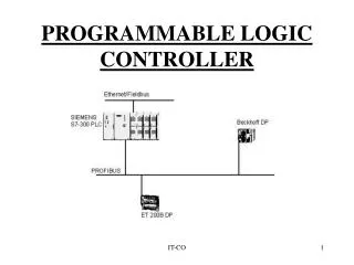
PLC System Components PLC - Program Input Module Central Processing Unit Output Module Sensors Actuators
Functions of a CPU • Reads input data from various sensing devices • Executes the stored user program from memory • Sends appropriate output commands to control devices
Input and Output System • Provides the physical connection between the outside world and the CPU • Discrete inputs/outputs are the most commonly used
Input Devices • Selector switches • Push buttons • Limit switches • Circuit breakers • Level switches • Relay contacts • Motor starter contacts
Input Identification • Input Word IW0 - IW2 • Input Bit I0.0, I0.1, …, I0.7 • Input Bit I1.0, I1.1, … I1.7 • Input Bit I2.0, I2.1, …, I2.7
Output Devices • Alarms • Control Relays • Solenoids • Lights • Horns • Valves • Motor Starters
Output Identification • Output Word OW0 - OW1 • Output Bit O0.0, O0.1, …, O0.7 • Output Bit O1.0, O1.1, … O1.7
Flag Identification • Flags are Internal Relays • Flag Word FW0 - FW255 • Flag Bit F0.0, F0.1, …, F0.15 • Flag Bit F255.0, F255.1, … F255.15
Timer Identification • Timers are Internal PLC Timers • Timer T0 - T15
Programming Device Software PLC Program Memory Acknowle-dgements (Sensors) Control Elements (Switches) Input Modules (Input Cards) Central Control Unit (Single or Multibit Processor) Output Modules (Output Cards) Final Control Elements (Relays, Solenoids, Indicators) Sensoric Processoric Actoric System Unit of a PLC
Selecting a PLC • Number of Inputs and Outputs • Types of Software Languages • Types of Operator Interface • Mathematical Calculations • Analog Input and Output • Communication with other PLCs and Computers • Ease of Maintenance • Ease of Programming