Download
1 / 8
80 likes | 202 Vues
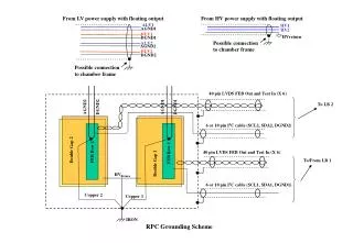
HV for SM surface testing. 2 nd Workshop on the Detector Control System for TRD University of Tsukuba Kengo Watanabe. Status. Iseg HV ・ Drift: 4 modules with 8 channels each ・ Anode: 1 module with 32 channels (Two independent modules with 16 channels)

E N D
HV for SM surface testing 2 nd Workshop on the Detector Control System for TRD University of Tsukuba Kengo Watanabe
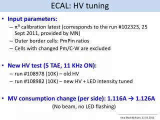
Status • Iseg HV ・Drift: 4 modules with 8 channels each ・Anode: 1 module with 32 channels (Two independent modules with 16 channels) ・Communication between devices and client has been established • FSM ・Standard HV state diagram plus error state implemented ・Panels for detector oriented nodes are ready
Iseg HV • Operation by PVSS ・Iseg OPC server can communicate to Iseg devices ・PVSS can communicate to Iseg devices through the Iseg OPC server • Available data points ・Set and monitor the state of device’s power ・Set and monitor the voltage and the current values ・Monitor the ramping and the trip state
Standard HV state diagram For stack and top For channel and layer
TRD HV top panel FSM State Indicator Simple monitoring panel open Crate Control Recipe Value Module setting panel
Simple monitoring Panel For Anode For Drift
Single Channel Panel FSM State Indicator Voltage and current indicator Trending monitor Setting Panel
Planning • Improve ramping state behavior ・Automatic chamber conditioning algorithm ex. Stop ramping near the trip value • Fix some FSM instabilities ・Unexpected states show up from time to time • Integrate into main DCS project (Jorge) • Install HV project to Munster