Download
1 / 27
280 likes | 445 Vues
Electron probe microanalysis. Variable Pressure / Environmental SEM Operation. Revised 2-21-12. What ’ s the point?. Traditional SEMs and microprobes operate at high vacuum.

E N D
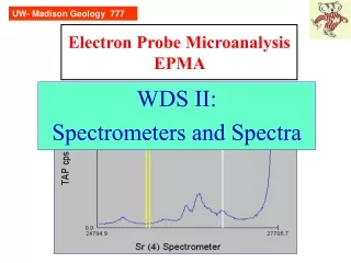
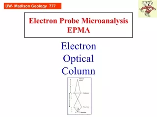
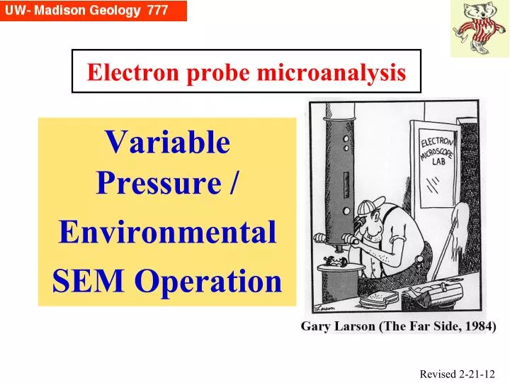
Electron probe microanalysis Variable Pressure / Environmental SEM Operation Revised 2-21-12
What’s the point? Traditional SEMs and microprobes operate at high vacuum. Today, however many/most SEMs being sold are versatile in being able to operate both at high vacuum, and a lower vacuum, where any gas including water vapor may be present. This presents new opportunities for examining specimens that otherwise would be difficult to examine. HOWEVER, there are serious difficulties when attempting to use EDS in the variable pressure mode.
Not to belabor “the point”But … Compared to electron probes, SEMs are very easy to use …. Which means that people will stick anything and everything into them! …. And people with little or no training will push buttons to generate data (=EDS) which they have no business doing! … And possibly generating data that is not correct.
Vacuum • Traditional SEMs and electron probes have operated with vacuums in the range of 10-3 Pa (10-5 Torr). • This was for several reasons: • protecting the electron gun (subject to oxidation and ruin) • keeping the beam of electrons tight to reach good spatial resolution (the gas molecules would interact and cause scattering--both elastic and inelastic)
Why use a poorer vacuum? • Sometimes you want to look at things that are naturally moist or wet -- biological specimens or clays -- and under the normal high vacuum SEM they become dried out and lose important features you want to view and document. • There has been an experimental undercurrent from 1960, attempting to image wet material, by modifying in an SEM, and • sandwiching the liquid between 2 thin carbon film, or • using a special substage, a closed box enclosing the sample and BSE detector, with a tiny aperture for the electron beam to enter, and a valve where water could be leaked in
Another benefit of poorer vacuum One critical feature of high vacuum SEM and EPMA was that samples either had to be conductive or conductively coated. However, if there is a poorer vacuum, there are enough gas molecules in the chamber that interact with both incident electrons and (mainly) emerging backscattered and secondary electrons, that become ionized, and produce a cloud of cations that neutralize any charging (bleed the electrons to the ground). Thus, having a poorer vacuum can become a tool to examine insulating specimens…though there are some serious drawbacks regarding EDS.
VPSEM and ESEM • Today there are two distinct varieties of SEM operating in this manner: • the “Environmental SEM” (trademark of Philips/FEI/ Electroscan), which can operate up to 2700 Pa in chamber and has a propriety secondary electron detector. For many years it was the only one that could operate with liquid water stable. • the variable pressure SEM sold by the other SEM companies, which are limited to a maximum pressure of ~266 Pa and may not have a special secondary electron detector (instead using BSE detector). • But BOTH have same general features for the most part.
Newbury, 2002 The “skirt” and its importance In a traditional SEM, 100% of the incident electrons land at a very tiny spot. But with VPSEM, they scatter as they come down and create a wide circular region called the “skirt”
Newbury, 2002 The “skirt” and its importance • For imaging, the skirt acts as a source of noise and degrades slightly the image -- not a big problem • However, for X-ray microanalysis (EDS), there are significant problems because spurious x-rays can easily be generated up to tens to hundreds of microns away, depending on the gas pressure -- a big problem -- as discussed by Dale Newbury in his 2002 article
The “skirt” This image shows graphically the “skirt” in the form of luminescent gas inside a VPSEM. The upper image is cross sectional view, whereas the bottom is looking normal to the beam. Note the small very bright center spot, a ~75 um bright diameter halo, and a ~250 um dimmer halo. Goldstein et al, 2003
The “skirt” Analogy (bottom image): You are on a foggy road and looking at the beam of an oncoming car headlight, diffused/ scattered thru the fog. Now consider yourself the specimen and the light coming at you is the package of electrons coming down the column at you… Goldstein et al, 2003
The “skirt” The skirt is extremely important to understand; its radius rs can be estimated from a simple analytical model (Danilatos, 1988): where GPL is the gas path length (=working distance) in meters; p is pressure in Pa; T is in degrees K, Z is atomic number of gas, and E is E0 in volts. rs is in meters…
The “skirt” Fig 5.20. Plot of beam broadening (skirt radius) as function of gas species and pressure. The gas path length is 5 mm and beam energy is 20 keV Fig 5.21. Plot of beam broadening (skirt radius) as function of gas path length (GPL) and beam energy in helium. Goldstein et al (2003)
EDS errors due to the skirt-1 Consider a standard block with Fe metal in a brass holder and a piece of Zr nearby (above left image). Under normal high vacuum, if the 20 kV electron beam is focused on the Fe about 50 microns in from the edge, the EDS pattern is as expected (above right), showing essentially only Fe Ka-Kb and Fe La Goldstein et al 2003, Fig 5.22
EDS errors due to the skirt-2 Now bleed in 20 Pa of air (above left) and even though we haven’t moved the beam, we are now seeing Cu and Zn from the brass holder in the EDS spectrum. Increase gas (air) pressure to 50-110 Pa and we now see also the Zr La from the Zr metal 500 microns away! Goldstein et al 2003, Fig 5.22
Detectors for VPSEM-ESEM Having gas present inside the vacuum chamber presents a major problem for the traditional E-T (Everhart-Thornley) SE detector. That detector has a high (e.g. +10 kV) bias on it, and would immediately arc over, blowing out a fuse (if you are lucky). So a VPSEM-ESEM can instead use its BSE detector without that problem -- but the image is somewhat washed out. OK but not great, as the fine detail of the surface is muted.
Goldstein et al, 2003 Detectors for VPSEM-ESEM A better detector is above, where the collisions of the emitted secondary (and backscattered) electrons with the gas molecules is used advantageously, producing an avalanche effect (=gas amplification) with electrons being attracted to a + bias electrode. This yields a secondary electron image. The detector is called a GSED or ESED.
ESED Detector for Hitachi VPSEM-1 BSE ESED In 2007, we upgraded our SEM to a 2nd generation Hitachi Environment Secondary Electron Detector (ESED) and have different/improved images acquired in VPSEM mode. BSE: little/no shadowing, can lose topo ESED: directional (shadowing), topo enhanced
ESED Detector for Hitachi VPSEM-2 • To improve the image, you can modify your conditions: • Lower voltage (dropped from 15 to 5 keV) • Drop the stage (=increase the working distance) from 10 mm to 25 mm, to give a greater depth of field • Increase the gas pressure from 25 to 40 Pa
@ * Wet Samples • In normal high vac SEM, water present at low pressure and room T (*) is strongly out of equilibrium and will evaporate (and be pumped out) quickly. • However, for a “true” ESEM, you can set the pressure to 2600 Pa (@) and stabilize liquid water in your sample, so there is no evaporation and change in the materials properties or features you are imaging. • However, a VPSEM (like our Hitachi) cannot reach 2600 Pa, so the only alternative would be to install a cold stage that would keep liquid water meta- stably, slowing the evaporation (<-------)
Particles! • While we’re discussing Hitachi SEM operation, it is important to point out a major difference with the electron probe • In the e- probe we examine flat polished samples because they must be, so there is constant path length for the absorption correction. • But the SEM is so flexible you can put anything in it, e.g. lots of particles of different sizes and shapes • Q: What would be the effect on the path length for a jagged homogenous particle? • A: You would get different compositions depending upon where you put the beam. Light elements would be particularly absorbed and incorrect.
Low Voltage Where imaging is concerned, sometimes it pays to experiment with E0… WHY? The issue is spatial resolution. Recall that the electrons scatter, and with higher E0, they have more energy and will scatter further from the “landing point”. It is thus a balancing act between having a detector that is sensitive to low energy electrons (BSE detector, right?) and enough E0 to give a strong enough signal to give a “good enough” image (Along similar lines, lowering the beam current also helps to give less beam electron scattering…but the signal will be weaker.) But lowering E0 of course creates complications with EDS…
VP SEM Applications in Weeks Hall • Imaging forams, some which may have carbon isotope measurements (Clay Kelly group) • Imaging Zebra mussels prior to carbon isotope analysis (Dana Geary group) • Evaluating synthetic nanoparticles (size mainly) (Nita Sahai group) • locating K-feldspars in a population of grains on carbon tape, for Ar-Ar dating (Brad Singer group) • EBSD (need there to be no coating on surface for optimal signals) (Laurel Goodwin and Basil Tikoff groups)
VP SEM Applications in Weeks Hall • Rapid identification of minerals in uncoated mounts (everyone!) • Imaging slightly wet samples: fault gauge from underwater zone, from California (Laurel Goodwin group) • Imaging sheared sediment samples” (Harold Tobin group) • Imaging very wet samples: microbial cultures (Eric Roden group) -- would need a cold stage to do this
Operational Issues • Use the least amount of air you can get away with; start with ~20-25 Pa but increase if still have charging; if using ESED detector, experiment with higher pressures • Have exposed the least amount of non-conductive surface, especially glass; surround area of interest with conductive tape if at all possible. Give the electrons an easy path! • Be very wary of EDS data acquired on particles, and particularly in VP mode! Only consider such data to be very qualitative. If you wish to be more quantitative, you MUST acquire standards of known composition similar to the unknowns and spend time studying them FIRST.