1 / 0

Packet Switching

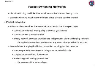
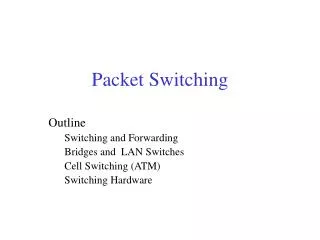
Packet Switching. What is a network?. Network: a collection of computers, each with its own unique ID (address), so that each computer can send a message to any other computer in the network. Is Ethernet a network? Is 802.11 a network?. Outline. Why we need switching

jara
Télécharger la présentation

Packet Switching

An Image/Link below is provided (as is) to download presentation Download Policy: Content on the Website is provided to you AS IS for your information and personal use and may not be sold / licensed / shared on other websites without getting consent from its author. Content is provided to you AS IS for your information and personal use only. Download presentation by click this link. While downloading, if for some reason you are not able to download a presentation, the publisher may have deleted the file from their server. During download, if you can't get a presentation, the file might be deleted by the publisher.

E N D

Presentation Transcript


  1. Packet Switching

  2. What is a network? Network: a collection of computers, each with its own unique ID (address), so that each computer can send a message to any other computer in the network. Is Ethernet a network? Is 802.11 a network?
  3. Outline Why we need switching Store-and-Forward Switches Datagram Switching Virtual Circuit Switching Source Routing Switching Bridges and Extended LANs Multicasting in LANs
  4. Full-mesh Ethernet Token Ring Directly connected networks Problems with these networks!
  5. Why We need switching/forwarding We can’t connect all the computers in the Internet by using directed links. Scalability Ethernet can have 1024 hosts. Ethernet can span 2500 m. Commercially not viable. Not required. Not every computer talks to every other computer. Small directly connected networks are connected by intelligent devices known as switches, which do switching/forwarding
  6. Switch Input Output ports ports What is switch? 1 1 forwards packets from input port to output port Advantages cover large geographic area (with latency though) support large numbers of hosts (scalable bandwidth) 2 2 3 3
  7. Switch to connect LANs Different types of switches Full-mesh with switch
  8. Our focus (for the moment) Consider point-to-point links for now We will come back to multi-access networks later So, what IS switching? Basically, what method do I use to move packets from one switch to another until the destination is reached Most Common: Datagram, Source routing, Virtual circuits
  9. Datagram Switching Internet uses this model. Very simple model. Also referred as connectionless model, hence no connection setup phase. Every switch maintains forwarding table or routing table. Between the same source & destination pair, different packets might take different routes. Usually when forwarding tables change.
  10. Host D Datagram Switching(cont..) Host E 0 Switch 1 Host F 3 1 Switch 2 2 Host C 2 3 1 0 Host A 0 Switch 3 Host B Host G Switch 2 Table 1 3 2 Host H
  11. Datagram Switching (contd) How does switch know the routing table? Using routing protocols such as distance vector, link state etc.. routing protocols. (Next chapter) Routing protocol should dynamically update routing table due to link and/or node failures. Fault tolerant against link and/or node failures. (Assuming no network partition.) Temporary disruption of data flow occurs while routing tables are updated.
  12. Source provides the information required for switching at every switch (places it in the packet header). One approach could be to providing ordered ports list at each switch. Source Routing Host E 0 Switch 1 Host F 3 1 Switch 2 2 Host C 2 3 1 0 Host A 0 Switch 3 Host B Host G 1 3 2 Host H
  13. Disadvantages The source needs to know the network topology Headers can be very long (variable sized) Three ways to handle header at each hop Header entering D C B A D C B A Ptr D C B A switch Header leaving A D C B D C B Ptr D C B A switch rotation stripping pointer
  14. Flow Identification Assume you want to guarantee some type of quality of service (minimum bandwidth, maximum end-to-end delay) to a user We will call a flow to be the sequence of packets generated by one user in one application Before you do that, you have to distinguish the packets of one “user” from another “user”, since they have different requirements (bandwidth, delay) Each output link would have a queue of packets per user How to efficiently separate packets into all these queues?
  15. Flow Identification Continued… How to separate packets of one user and another? Perhaps look at addresses: Each packet has a source and destination address Separate packets according to (source,destination), i.e., one packet queue per pair How to quickly do this separation? I.e., if a packet is received, to which queue I should add it?
  16. Flow Identification, search tree How about a search tree, indexed by (S,D) Searching takes multiple steps (O log N, N is the number of queues), too slow
  17. Flow Identification – (S,D) table We need fast access to the queues How about a table, (big array) indexed by (S,D)? It would require 264 entries! 264
  18. Hash Table (key: (S,D) ) Flow Identification – hash table We need a fast but small table Perhaps a hash table (say, 1000 entries) Hash(S,D) gives you the “bucket” or table entry where the queue of the packet is How to handle collisions? You have to revert to search trees for each bucket Slow!
  19. Flow Identification – flow label We still need a fast but small table Say, 1000 entries Each flow can have a label that is used as an index into that table. Note that there are more than 1000 flows in the world But a single router may be involved in only about 1000 flows at a time Hence, flow labels could be local to the router These are known as “virtual circuits” BTW, they are not used in the Internet (in general)
  20. Virtual Circuit Switching Also referred as connection-oriented model. Explicit connection setup (and tear-down) phase All packets follow same route as the setup message route. Resources may be reserved along this path The telephone network performs something similar for voice calls
  21. Virtual Circuit ID’s Each virtual circuit (VC) has a unique virtual circuit identifier (VID) in each link along its path It is determined locally by the switch incident on that link (receiving side of link) and is chosen independently of other values along the path. No two VC’s on the same link (port, interface) can use the same VID Note: VID's are reused periodically, since they are bounded and small (they are the index into a table), VID : 0 .. v-1 for some constant v Switch 1 Switch 2 vid = 10 vid = 2 vid = 29 Host B Two circuits: one from E to F another from A to B Host A vid = 11 vid = 100 vid = 9 Host E Host F
  22. Virtual Circuit Table Each switch has a table Table has an entry for each virtual circuit going through it Contains Input port (interface or whatever you want to call it) Input VID Output port Output VID table index (input port, input VID) vid = 10 vid = 2 Output Port 2 vid = 11 Input Port 0 Input Port 1 vid = 9
  23. Note on VC table organization The VC table is organized for quick access I.e., it is a big two dimensional array, whose indices are [input port, input VID] The contents of each element in the array is a record with all the necessary information about the VC Output port Output VCID Credit card information … 
  24. VC Data Transfer Phase Each Data Packet carries the VCID in its header Data Transfer Phase: Switches use Virtual Circuit Tables to forward data. The VCID in the header changes at every hop
  25. VC: Data Transfer Phase Host E 0 Switch 1 Host F 3 1 Switch 2 2 Host C 2 3 1 0 Host A Switch 1 VC Table Switch 2 VC Table 0 Switch 3 Host B Host G 1 3 2 Switch 3 VC Table Host H Data( ) message
  26. Virtual Circuit Switching (steps) Virtual Circuit (VC) Step up or signaling phase: Source (i.e. host A) sends setup() message towards destination (i.e. host B). Destination replies back with ack() . All the switches along the path between source and destination create Virtual Circuit Tables at the end of this phase. Note that forwarding tables are necessary for the setup message, just like in datagram routing !!!!
  27. VC: Setup or signaling Phase Host E 0 Switch 1 Host F 3 1 Switch 2 2 Host C 2 3 1 0 The VC tables are emptyinitially. Host A Switch 1 VC Table Switch 2 VC Table 0 Switch 3 Host B Host G 1 3 2 Switch 3 VC Table Host H Setup( ) message Ack() Message
  28. VC Vs Datagram switching
  29. Quality of Service Summary Easier to guarantee throughput to each connection in VC’s than using datagrams E.g., serve each VC on an output line using round-robin (or weighted round robin) In datagram, there is no way to determine which “connection” a datagram belongs to In datagram, there is no mechanism to inform the switch of the QoS desired.
  30. ATM ATM (Asynchronous Transfer Mode) Standard for a “world-wide” network (never did grow much, but isolated “islands” of ATM exist) Supports various forms of quality of service Uses VC to reserve resources For switching efficiency, uses small fixed size packets (53 bytes)
  31. Bridges and Extended LANs Switches between LANs are called Bridges. LANs connected by bridges are known as Extended LANs. Bridge makes many LANs look like one LAN. LAN 1: Consists of many hosts connected via “hubs” (multi-way repeaters), the hubs are not drawn. A B Port 1 LAN 2 Bridge Port 2 X Y Z
  32. Bridges and Extended LANs Hosts are not aware of bridges (transparency). Host from one LAN can send data to host in different “LAN directly”. A silly scheme: bridges copy every message they see and forward a copy over all of its other ports. Can we improve this?
  33. Optimization: Learning Bridges Bridges maintain forwarding table. Bridges forward frames when necessary. Learn table entries based on source address of the received frames. Binding between host id and bridge port number is “soft state” (eventually erased) A 1 A B C 1 Bridge X 2 2 X Y Z Packet from Host A to Host X
  34. Example: Learning Bridges M N O L B2 B1 B3 B4 K B8 I P B5 B6 B7 J Bridge Host I LAN
  35. Example: Learning Bridges Assume initially all bridges forwarding tables are empty Host I sends data message to Host J: This data message is flooded to every LAN. Why? Because no one knows where J is! Due to which, every bridge learns about host I location and creates forwarding table entry for Host I.
  36. Example: Learning Bridges M N O L IJ B2 I I B1 IJ IJ B3 I I I IJ B4 K B8 I I I I P B5 B6 B7 J Bridge Host I LAN
  37. Example: Learning Bridges Host J then sends data message to Host I: Since all bridges have an entry for host I, message goes only through Host J B7B8 B3 B2 B1 Host I Only these bridges have now an entry for Host J. All other nodes do not, e.g., B4 does not forwarding table entry for Host J. Note that from now on (until the lifetimes expire) all data messages between Host I and Host J go only through the LANs on the path from Host I to Host J.
  38. Example: Learning Bridges M N O L B2 J I J I B1 JI B3 I J I I B4 K JI B8 J I P I I I JI B5 B6 B7 J JI J Bridge Host I LAN
  39. Example: Learning Bridges(cont) Host K sends a data message to Host J: The nodes seeing this data message are B4 B5 B6 B3 B8 B7 only these nodes learn Host K location. Host k packet has been flooded in a limited fashion.
  40. Example: Learning Bridges M N O L B2 J I J I B1 B3 K I J I KJ K I KJ B4 K B8 K J I P I K I K I K B5 KJ B6 B7 J J Bridge Host I LAN
  41. Loops could make frames to traverse indefinitely in extended LANs. Loops:Spanning Tree Algorithm A B B3 C B5 D B7 B2 E F B1 G H B6 B4 I J
  42. General Introduction How can extended LANs have loops: LANs might be administrated by different persons. Loops built into network to provide redundancy in case failure. Spanning Tree algorithm, developed by Radia Perlman, avoids loops. IEEE 802.1 specification for LAN bridges is based on this algorithm. This algorithm creates spanning tree of bridges. Distributed, dynamic algorithm.
  43. A Loop Free Extended LAN B B3 C B5 D B7 K B2 E F B1 G H B6 B4 I J removed port
  44. Algorithm Overview Each bridge has unique id (e.g., B1, B2, B3) and also assume Bi < Bj if i < j. smallest id bridge is selected as root. Algorithm creates a spanning tree rooted at smallest id bridge. Smallest ID root
  45. A Spanning Tree B B3 C B5 D B7 K B2 E F root B1 G H B6 B4 I J Path to root
  46. Main Idea Assume you had knowledge of the whole topology (you don’t!) Selects the smallest ID bridge as the root. Each bridge “calculates” its shortest path to the root bridge. Its “parent” is the next-hop bridge to the root
  47. A Break ties? B B3 C B5 D B7 K B2 E F root Parent relationship B1 G H B6 B4 I J
  48. Designated Bridges For each LAN we select one bridge as the designated bridge(DB). Designated bridge is the one that is closest to the root. (In case of tie smallest ID bridge wins).
  49. DB for LAN A, B A B B3 C B5 DB for LAN K DB for LAN c D B7 K B2 E F root B1 G H DB for LAN J, I B6 B4 I J Break ties?
  50. Port Selection Which ports to keep and which to remove? Keep the port leading to your parent Keep the port leading to a LAN where you are the designated bridge Eliminate all others
  51. DB for LAN A, B A Designated Bridges X B B3 X C B5 DB for LAN K DB for LAN c D B7 K B2 E F root B1 G H DB for LAN J, I B6 B4 X I J
  52. Distributed Solution: Configuration Messages Only the root periodically creates and sends configuration messages on all its ports (sent to an “all bridges” multicast address) These messages propagate from the root to all other nodes The # of hops traveled by the message indicate its distance to the root configuration messages (SID, RID, dist) with following information. SID: Sender’s ID. RID: Current root bridge ID (ignore for the moment). Dist: Distance (hop count) to root bridge
  53. (B3, B1,2) (B2, B1,1) (B7, B1,1) (B1, B1,0) (B1, B1,0) (B1, B1, 0) Spanning Tree A B Who should be the parent of B2, B3, B7 and B5? B3 C B5 D B7 K B2 E F Temporarily, you might choose the wrong parent. B1 G H B6 B4 I J
  54. Finding the Path to root When a bridge receives configuration message: If it comes from its parent Update my dist according to the parent (even if worse than before) Forward a copy with dist+1 to “all” neighboring LANs If not from its parent and the distance is worse than via parent, then throw away If not from parent and distance is less than via parent, then Set neighbor to be your new parent, set distance to neighbor’s distance + 1 Forward with dist+1 to all neighbors Note: when you forward a configuration message, it always states your current distance to the root, i.e., only forward configuration messages from your (perhaps new) parent!
  55. Designated Bridge G H B6 B4 I J How can B6 know that the designated bridge for LAN I is B4?
  56. Designated Bridge G H B6 B4 I J Each bridge hears the configuration messages sent from other bridges on the same LAN Hence, it can determine their hop count to the root and their bridge id Each bridge then determines if it should be the designated bridge of the LAN
  57. Best configuration message Is a message that I received from some neighbor better than the information I have right now? (i.e. who should be the designated bridge?) My configuration message (SIDme, RIDme,distme) is better than the neighbor’s message (SIDneigh, RIDneigh,distneigh) if: Message root with smallest ID. i.eRIDme< RIDneigh Message with same root ID but with shorter distance i.eRIDme= RIDneighbut distme< distneigh Root ID and distance are equal but the sending bridge has smaller ID. i.eRIDme= RIDneighand distme= distneighbut SIDme< SIDneigh
  58. What if no root right now? Initially each bridge thinks itself as the root. Initially every bridge creates and sends configuration messages. Once bridge realizes that it is no longer root, it stops creating configuration messages, it now has a parent, so it forwards the configurations messages from its parent. As before, when a bridge Bi receives a configuration message. Checks if new path is better than path via currently chosen parent. If new path is better, then Updates its own root to that of the message. Updates its parent to sender of the message Bi updates configuration message by adding 1 to the distance, and forwards it. Configuration messages are only forwarded if they come from the (perhaps new) parent
  59. (B2, B2,0) (B2,B1,1) (B1, B1,0) (B1, B1, 0) (B1, B1,0) Extended LAN Spanning Tree A B1 B2 B B3 B1 C B5 B1 B1 D B7 K B2 E F B1 G H B1 B1 B6 B4 I J
  60. Optimization Remember for each port what is the best config message you have heard on that port. You are the designated bridge of a LAN if The best config message you have heard on that LAN is not as good as your own information You have not heard config messages over that LAN for a long time. Thus, your record for that LAN is empty (no config message) and you become the DB of the LAN A bridge forwards configuration messages ONLY over ports for which it thinks it is the designated bridge (for efficiency) If any bridge does not receive configuration message after a period of time from its parent, it chooses as a new parent the neighbor who offered the best configuration message. If any bridge does not receive configuration message after a period of time from any port, it starts generating config messages claiming to be the root.
  61. Limitations of Bridges Does not scale spanning tree algorithm does not scale broadcast does not scale Does not accommodate heterogeneity Caution: beware of transparency Packets can be dropped (not so in a single Ethernet) Delays are longer and variable (fixed in Ethernet) Packet reorder may be possible (although unlikely, but impossible in Ethernet without bridges).
  62. I AM GOING TO SKIP MULTICAST
  63. Multicast in an extended LAN A multicast group is a set of hosts Any data addressed to the multicast group should be delivered to all these hosts Any host at any time can send a message to the group The sender need not be part of the group
  64. Multicast in Ethernet Ethernet has a range of addresses for unicast, and another range of addresses for multicast How do you become a “member” of the group? The host configures its interface to accept messages addressed to the group How do you send a message to the group? Simply set the destination address to be the address of the group.
  65. Efficient multicast in Extended LANs How to do efficient multicast in Extended LANs? (I.e. in LANs with bridges) Bridges propagate broadcast (and multicast) packets across every segment of the extended LAN Way too inefficient, especially for multicast applications with sparsely located receivers Find an efficient way of doing multicast and convert applications to use multicast How to do multicast better in Extended LANs?
  66. Single Spanning-Tree Multicast Routing A The extended LAN forms a TREE If bridges know which interfaces lead to members of a given group, they would forward the packets on those interfaces only G = group G member (receiver) B B3 C Arrows indicate the location of the group member What if a host in LAN E sends a message addressed to the group? B5 G D B7 K E F B1 G H B4 G I J
  67. Where are the receivers? How do bridges learn which interface lead to individual hosts? Bridges learn about hosts when the host sends a message. Bridges do not learn about inactive hosts. Problem: receivers don’t send data Thus, group members (i.e., hosts) periodically transmit a membership-report
  68. Multicast Table Multicast table of each bridge has the following row for each multicast group: (muticastaddr, (outgoing interface, age), (outgoing interface, age), … ) A member (host) of a group G sends a membership-report, source address = G (this distinguishes it from a regular data frame) destination address = “ALL-BRIDGES” multicast address. Bridge receiving this membership report will records this interface as an outgoing interface for group G forwards this report to other bridges (out all of its interfaces) in the extended LAN (why over all interfaces? I.e., why a flood?)
  69. Example A B B3 C B5 G D B7 K Arrows indicate the location of the group member Membership reports are forwarded over all links of a bridge E F B1 G H B4 G = group G member (receiver) I J
  70. Another example A B B3 C B5 G D B7 K Arrows indicate the location of the group member Membership reports are forwarded over all links of a bridge E F B1 G H B4 G G = group G member (receiver) I J What if a host at E sends a msg to group G?
  71. Summary Bridge algorithm (summary) If source address is a mcast group address (i.e. a report), record arriving interface as an outgoing-interface with an age of zero into the table entry for this mcast address and forward to all other interfaces. Periodically increment age of outgoing interface when age=expiry threshold, delete this outgoing-interface info from the table’s entry if no outgoing-interfaces remain, delete the entire entry If a packet arrives with multicast dest addr forward a copy on every outgoing-interface recorded in the table entry (if any) excluding the arriving interface
  72. Suppressing Membership Reports An efficiency improvement to suppress unnecessary membership reports Hosts send membership-reports as (G,G) This suppresses #membership reports to 1 per report interval per LAN because all other group members (hosts) on the same LAN heard the first membership-report (G,G), and will not send a report Bridge, on receiving a pkt with address (G,G) (bridges receive ALL packets, remember?) changes it to (G, all-bridges) and forwards to other interfaces
  73. Why change the destination? Assume member X of group G sends a membership report (G,G) over lan A Assume the bridge forwards it as (G,G) over lan B This will suppress the membership report of Y who is also a member of G The bridge will never know there is a group member in lan B Why does the router change from (G,G) to (G, “ALL-BRIDGES”)? A B X G bridge Y G
More Related